Case 1: PU Robot Basic Action Imitation Show
Case Introduction
Learn about the structure of the PU Robot and get familiar with its basic operations.
Teaching Preparation
| Name | Diagram |
|---|---|
| PU Robot Kit | 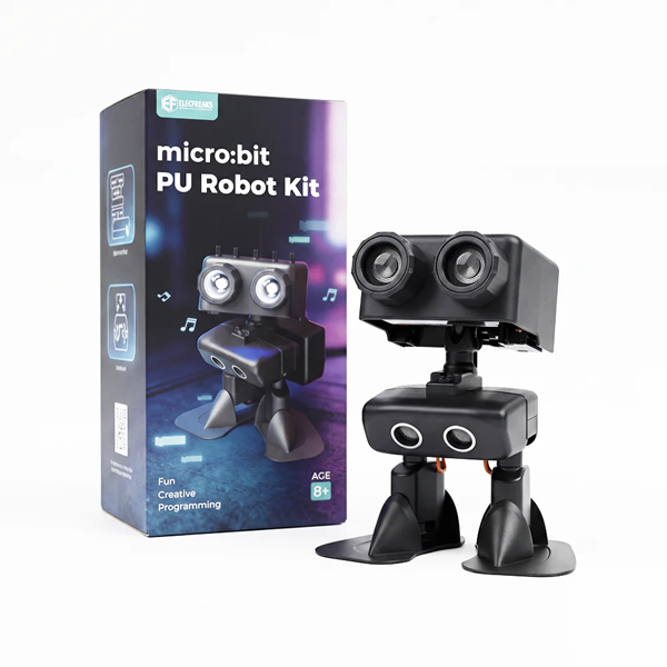 |
Course Objectives
- Recognize the basic components of the PU Robot and perceive the connection between technology and engineering design.
- Master the remote control operation of the PU Robot and develop hands-on manipulation skills.
Course Introduction
Today we welcome a special partner — the PU Robot. It has a flexible body and can perform many interesting actions. Would you like to meet it and play with it?
Learning Exploration
Component Exploration: The teacher guides students to observe the PU Robot in groups, focusing on the fully wrapped PU shell, head servo, and joint parts (preliminarily perceiving the 6-DOF flexibility). With simple explanations, students will understand the basic functions of each component.
Action Perception: The teacher controls the PU Robot with a remote controller to demonstrate basic actions such as walking, nodding, and kicking. Students are guided to observe the movement of the robot's joints, compare the similarities and differences between human and robot actions, and think about "why robots can perform actions similar to humans", preliminarily understanding the simple principle of "servo drive" to lay the foundation for subsequent remote control operations.
Control Basics: The teacher briefly explains the basic operations of the remote controller (forward, turn, stop, action switch), emphasizes key operation points, and guides students to initially perceive the correspondence between remote control commands and robot actions, preparing for hands-on practice in classroom activities.
Classroom Activities
Activity 1: Component Observation Task
| No. | Name | Description |
|---|---|---|
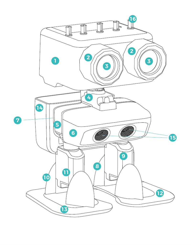
| 1 | Head Shell × 1 | Fixes the circuit board, battery and head servo; with building block pin adapter holes for connecting building blocks. |
| 2 | Lamp Holder Bracket × 2 | Fixes the lamp heads and installs them on the head shell. |
| 3 | Lamp Head × 2 | Realizes LED lighting effects. |
| 4 | Shoulder Bracket × 1 | Fixes the neck servo; connects the neck bracket and chest bracket. |
| 5 | Chest Bracket × 1 | Fixes the leg servos; connects the shoulder bracket and legs. |
| 6 | Front Cover × 1 | Fixes the ultrasonic sensor and connects to the chest bracket. |
| 7 | Rear Cover × 1 | Organizes and fixes wires; provides building block pin holes; can connect backpacks and other external building block parts. |
| 8 | Left Leg Bracket × 1 | Fixes the left foot servo. |
| 9 | Left Leg Protective Cover × 1 | Protects the left foot servo; connects the leg bracket and left foot. |
| 10 | Right Leg Bracket × 1 | Fixes the right foot servo. |
| 11 | Right Leg Protective Cover × 1 | Protects the right foot servo; connects the leg bracket and right foot. |
| 12 | Left Foot × 1 | Connects to the left foot servo to realize foot movements. |
| 13 | Right Foot × 1 | Connects to the right foot servo to realize foot movements. |
| 14 | Backpack × 1 | Connects to the rear cover and can hold items. |
| 15 | Ultrasonic Sensor × 1 | Measures the distance to obstacles. |
| 16 | Building Block Pin Adapter × 5 | Connects the head shell to external building block parts. |
| No. | Name | Description |
|---|---|---|
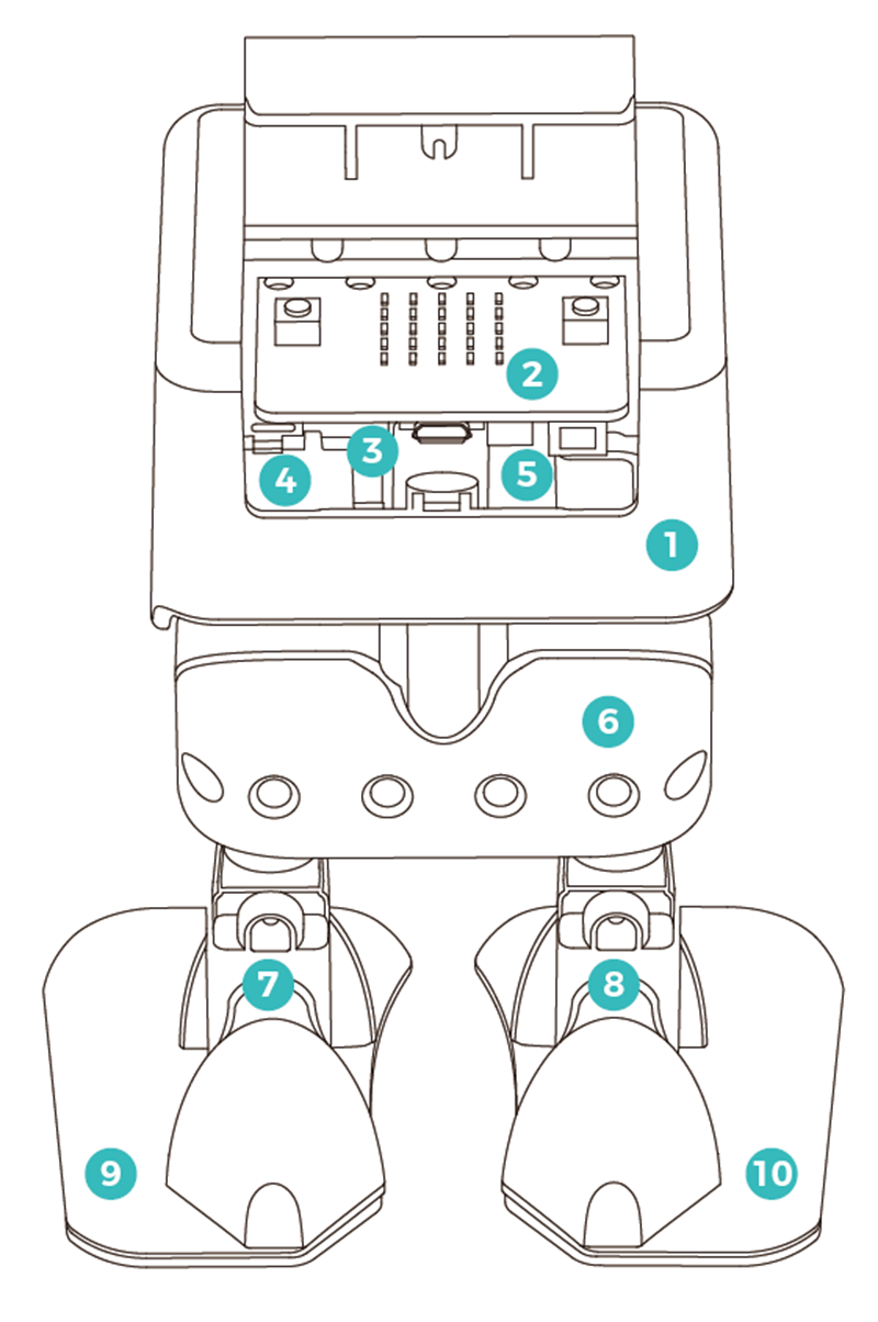
| 1 | Head Shell × 1 | Fixes the circuit board, battery and head servo; equipped with building block pin adapter holes for connecting building block components. |
| 2 | micro:bit Main Control Board × 1 | Controls the robot and its artificial intelligence functions. |
| 3 | Head Servo × 1 | Controls the robot to raise/lower its head. |
| 4 | Head Servo Bracket × 1 | Fixes the head servo. |
| 5 | Neck Bracket × 1 | Connects the neck servo and head servo to the head shell. |
| 6 | Rear Cover × 1 | Organizes and fixes wires; provides building block pin holes; can connect backpacks and other external building block components. |
| 7 | Left Leg Bracket × 1 | Fixes the left foot servo. |
| 8 | Right Leg Bracket × 1 | Fixes the right foot servo. |
| 9 | Left Foot × 1 | Connects to the left foot servo to realize foot movements. |
| 10 | Right Foot × 1 | Connects to the right foot servo to realize foot movements. |
Activity 2: Robot "Imitation Show"
| No. | Control Item | Function Description |
|---|---|---|
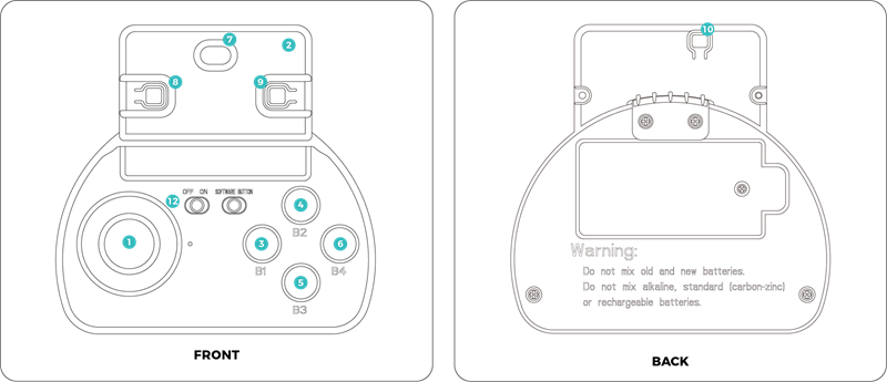
| 1 | Joystick | 1. Push the joystick forward/backward, and the robot will move in the corresponding direction. The greater the pushing amplitude, the faster the robot moves. 2. Tilt the joystick left/right, and the robot will turn in the corresponding direction. The greater the tilting amplitude, the larger the turning angle. 3. Press the joystick once, and the robot enters rest mode. 4. Tilt the joystick greatly left/right, and the robot will move sideways in the corresponding direction. |
| 2 | Micro:Bit Gesture Control | When controlling with the joystick, tilt the controller up/down to control PU's head to swing up and down; tilt the controller left/right to control PU's head to turn in the corresponding direction. |
| 3 | B1 Button | Activates the PU Robot to enter automatic driving mode, enabling autonomous walking or maze exploration. |
| 4 | B2 Button | Makes the PU Robot jump, suitable for football games and dance scenes. Do not press this button continuously; wait for the previous jump action to complete before executing the next jump. |
| 5 | B3 Button | Makes the PU Robot dance. When music is on, PU will dance to the music rhythm, and its LED lights will change colors with the beats. |
| 6 | B4 Button | Makes the PU Robot kick the ball, suitable for football game scenes. Do not press this button continuously; wait for the previous kicking action to complete before executing the next kick. |
| 7 | Micro:Bit Induction Logo | Touch the Logo area of Micro:Bit, and the PU Robot will randomly speak or sing. The content depends on its recent activity status, and the factory default behavior can be modified through programming. |
| 8 | Micro:Bit Button A | Increases the radio control channel, and the channel number will be synchronously displayed on the Micro:Bit screen. |
| 9 | Micro:Bit Button B | Decreases the radio control channel, and the channel number will be synchronously displayed on the Micro:Bit screen. |
| 10 | Micro:Bit Reset Button | Restarts the controller control program, and the radio control channel will be restored to the default value 6. |
| 11 | Micro:Bit A+B Combination Key | Press Button A and Button B simultaneously to display the current actual radio control channel (actual channel number = displayed value on the screen + 160). |
| 12 | Power Switch | Turns the controller power on/off. |
Summary & Sharing
Invite students to share their feelings of controlling the robot, talk about which components they have recognized and which operations they have learned. The teacher summarizes the key points of this lesson and encourages students to continue exploring the interesting functions of the robot after class.