Case 01 Wonderful Performance
Introduction
In this course, we will guide students through an in-depth exploration of the MakeCode graphical programming platform and learn how to import the XGO Rider programming library. Students will learn how to communicate with the XGO Rider via micro:bit and how to programme it to perform various performance actions.
Instructional Objectives
- Become proficient in the MakeCode platform and how to import XGO Rider library files.
- Learn to set up the serial port for communication between the micro:bit and the XGO Rider.
- Understand the basic concepts of serial communication.
- Learn how to program the XGO Rider to perform actions.
Preparing for Teaching
Before you start teaching, please make sure you have the following necessary items ready:
 | micro:bit V2 |
|---|---|
 | XGO-Rider |
 | USB Cable |
 | PC |
These materials will provide you with a complete experience and ensure that you can follow through and learn smoothly. If you are ready for the above, we can move on to the next step.
 The XGO Rider will need to be moved back and forth in small increments to maintain its balance after switching on, please do not place the XGO Rider on the edge of a table or in a dangerous place to avoid damage.
Teaching Process
Introduce
Many students are curious about robots and are eager to learn how they work and how they are controlled. This course teaches how to program and control the XGO Rider through a graphical programming platform so that it performs exciting show moves. Our goal is to make robot programming easy to understand, just follow the steps in this tutorial. Ready to explore the world of robot programming? Let's start this fun and challenging learning journey!
Exploration
- How do I write my first XGO Rider control programme?
- How does micro:bit communicate with the XGO Rider?
- What other actions would you like to add to the XGO Rider's performance mode?
Start Programming
Add XGO Rider packages
1. Go to “makecode.microbit.org”, click New Projects.

2. Enter the project name in the pop-up window and click Create.

3. Click on Extensions in the Code Drawer, type XGO Rider in the search box on the pop-up screen and click on the search icon, then click on the XGO Rider repository when it is displayed.

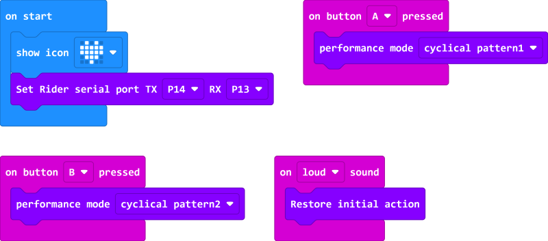
Samples Program

Link: https://makecode.microbit.org/_725V2h8cxd2h
 Because XGO Rider's Performance Mode has forward and reverse, please place XGO Rider on a wide, flat surface.
Download Program
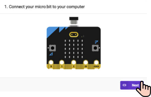
1. Use the USB cable to connect the PC to the micro:bit V2.

2. After successful connection, a disc drive named MICROBIT will be recognised on the computer.

3. Click in the left down side, select Connect Device.

4. Click 。
。

5. Click .
.

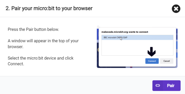
6. Select BBC micro:bit CMSIS-DAP in the pop-up window, and then select Connect, so our micro:bit has been successfully connected.

7. Click Download programme.

Teamwork and Presentation
Students are divided into teams and work together to program the XGO Rider performance mode.
Students are encouraged to co-operate, communicate and share their experiences with each other.
Each team will have the opportunity to present and demonstrate the XGO Rider they have programmed to the other teams.
Expected results:

Summary and Reflection
- Review the content of this course to confirm the knowledge and skills that students have mastered, including the MakeCode platform programming style, importing XGO Rider library files, XGO Rider and micro:bit motherboard communication serial port setup commands, and XGO Rider show mode commands.
- Lead students to discuss problems and difficulties encountered during the production process and how they were resolved.
- Think about how to further optimise the programming to make the XGO Rider perform better.
Extended Knowledge
Serial communication in the micro:bit V2 is implemented through its on-board ARM Cortex-M0+ microcontroller, which supports serial communication through GPIO (General Purpose Input Output) pins. The following is a detailed description and explanation of the TX (Transmit) and RX (Receive) pins for serial communication in the micro:bit V2:
TX pin
- Pin Location: In micro:bit V2, the TX pin is usually P1. However, the TX pin is defaulted to P14 for the serial communication between micro:bit and XGO Rider. Function: The TX pin is normally P1 in micro:bit V2 .
- Function: The TX pin is used to send data. When the micro:bit needs to send data to another device (such as a computer, another micro:bit, or other device that supports serial communication), it will output data through the TX pin.
- How it works: In serial communication, data is sent in serial form, i.e. bit by bit. When sending data, the TX pin generates an electrical signal according to the protocol of serial communication (e.g. RS-232, TTL, etc.).
RX pin
- Pin Location: In micro:bit V2, the RX pin is usually P2. However, micro:bit and XGO Rider serial communication RX pin defaults to P13. Function**: The RX pin is used to generate an electrical signal according to the serial communication protocol (e.g. RS-232, TTL, etc . ) .
- Function: The RX pin is used to receive data. When an external device sends data to the micro:bit, the data will be input to the micro:bit via the RX pin.
- How it works: When receiving data, the RX pin monitors the electrical signals sent by the external device and converts them into digital signals that can later be processed by the micro:bit's microcontroller.
Configuration and use of serial communications
- Initialising the serial port: When programming, it is usually necessary to initialise the serial port, setting parameters such as baud rate (i.e. the number of bits transmitted per second), data bits, stop bits and parity bits.
- SEND DATA: The TX pin can be programmed to send strings or bytes. 3.
- Receiving data: Similarly, the data received on the RX pin can be read using the programming interface.
Notes
- Cross Connection: When connecting the micro:bit to another device through the serial port, you need to make sure that the TX pin of the micro:bit is connected to the RX pin of the other device and vice versa.
- Voltage Matching: The micro:bit's GPIO pins use a 3.3V logic level, so if connecting to another device, you need to make sure the voltages are compatible to avoid damaging the micro:bit.
- Power Management: When using serial communications, if the micro:bit is powered by an external power supply, you need to ensure that the supply voltage and current are within safe limits. Serial communication is a very common way of communicating between electronic devices, and the micro:bit V2 provides this capability through its TX and RX pins, making it possible to exchange simple data with other devices, making it ideal for education, prototyping, and a wide variety of electronic projects.