Power Module
Introduction
Features
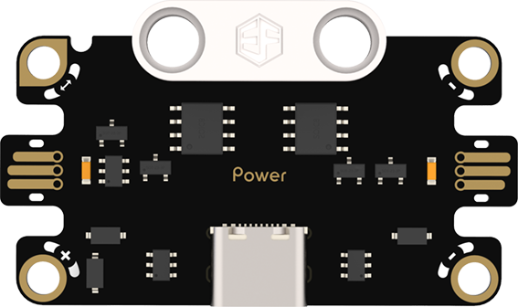
Power Module: It is responsible for power supply and management of the entire system, stably outputting voltage and current suitable for each module to ensure stable system operation.
Specifications
| Item | Parameter |
|---|---|
| Name | Power Module |
| SKU | EF16008 |
| Connection Type | Power Supply |
| Operating Voltage | 5V |
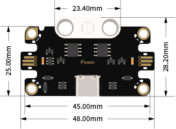
| Dimensions | 48.00mm×31.40mm (L×W) |
Appearance and Dimensions
Product Links
None
Usage Tutorial
Hardware Connection Diagram
Note: Please prepare a 5V power supply separately.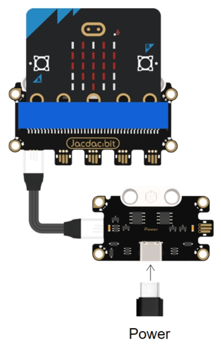
Methods to Turn On/Off Port Power Output
Go to the [Web Device Debugging Interface](https://jacdac.github.io/jacdac-docs/dashboard/)
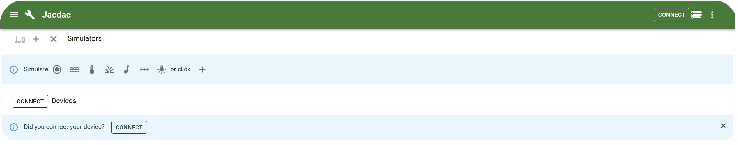
2.Connect the micro:bit to a computer via a USB data cable, click "Device Dashboard" and then "Connect" to establish a device connection.
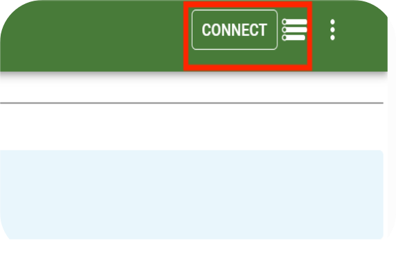
3.Click "Connect USB".
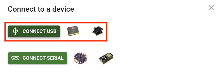
4.Select the corresponding serial port and click "Connect".

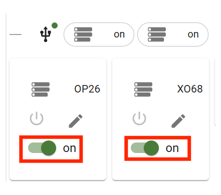
5.You can turn on or off the power output of the power module's ports in the web debugging interface.
If the power output of a port is turned off, the port's LED indicator will turn off. Conversely, if the power output of a port is turned on, the port's LED indicator will turn on.
Hardware Connection Diagram
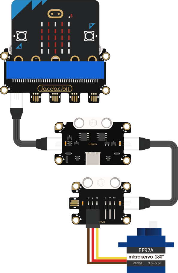
Note: The power module needs to be connected to a 5V power supply.
Programming Software
MakeCode Programming
Step 1: How to Add Jacdac Extension
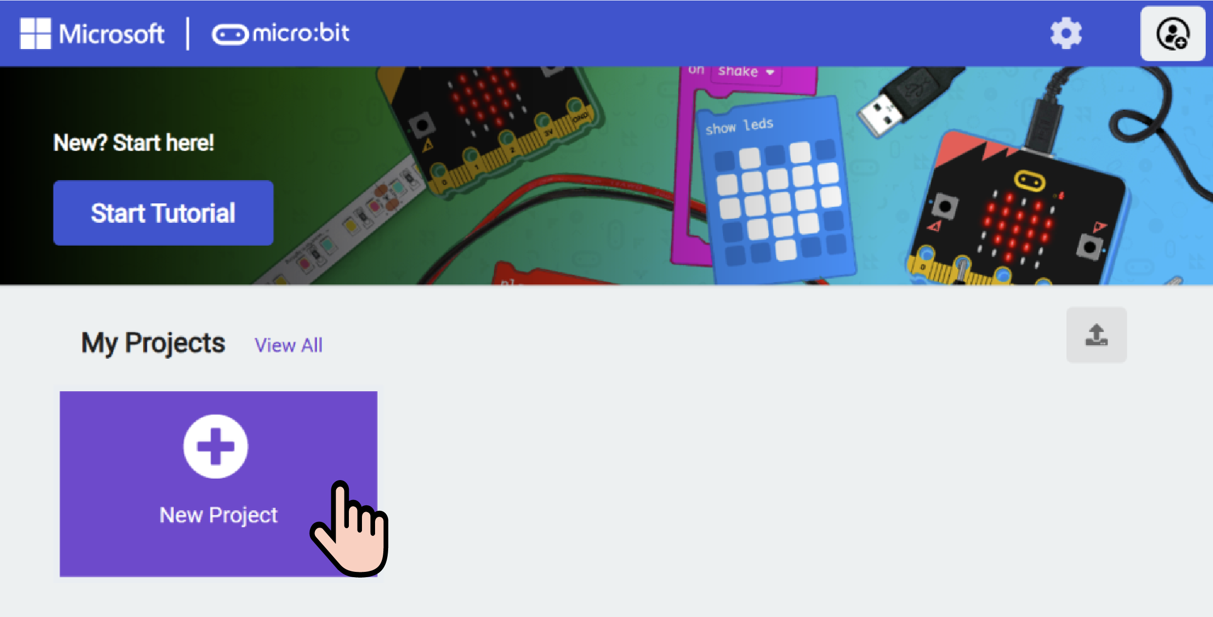
- Go to Microsoft MakeCode and click "New Project".
- Enter the project name in the pop-up window and click "Create".

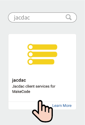
- Click "Extensions" in the code drawer.

- Enter "Jacdac" in the pop-up interface, click the search icon, and select the Jacdac library as shown.
Step 2:
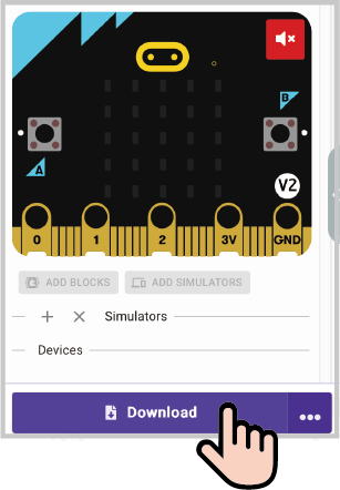
- Connect the micro:bit to the computer with a data cable. Note: If the micro:bit runs a Jacdac program for the first time, please pre-install a blank Jacdac program on the micro:bit first; otherwise, skip this step.
- Connect the sensor. MakeCode will automatically recognize it and simulate its status in real time in the simulation area.
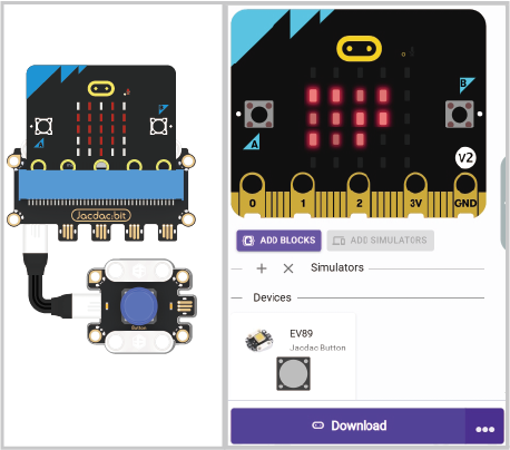
- Click "ADD BLOCKS" for the sensor extension module. Note: When connecting a new sensor, repeat the operation of clicking "ADD BLOCKS" for the sensor extension module.

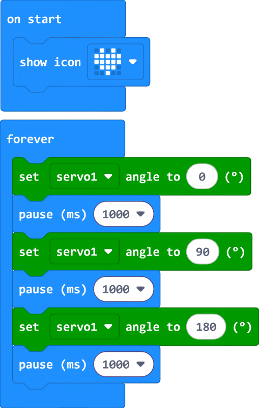
Program Code Example
Reference Program Link
https://makecode.microbit.org/_bW1btg9VzLg9
You can also download and run it via the embedded link:
Result
The servo rotates from 0° to 90°, then to 180°, and then back from 180° to 0°.