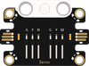
Micro:bit Related ProductsJacdac SeriesJacdac Energy Experiment KitCase 9: Internal Combustion EngineOn this pageCase 9: Internal Combustion EngineIntroductionHold down the Jacdac external button module, and the 360° building-block servo rotates continuously. Through a crank-connecting rod mechanism, the rotational motion is converted into the piston's reciprocating linear motion, simulating an internal combustion engine firing up and running. Release the button, and the servo stops — simulating engine stall. Button pressed = throttle engaged; released = engine off.Learning ObjectivesLearn about the internal combustion engine and understand how it converts the chemical energy of fuel into mechanical energy.Understand the crank-connecting rod mechanism — the core mechanical structure that converts between rotational and reciprocating motion.Explore the energy conversion chain — chemical energy → thermal energy → kinetic energy → mechanical energy, experiencing the transformation of energy forms.Required MaterialsItemImageQuantitymicro:bit V21Jacdac Expansion Board1Jacdac 25cm Connector Cable2Jacdac Button Sensor1Jacdac Servo Module1360° Building-Block Servo1USB Cable1Jacdac Energy Practice Kit Building Blocks1Assembly StepsModel PrincipleCrank-Connecting Rod MechanismThe crank-connecting rod mechanism is the most critical transmission component in an internal combustion engine, consisting of three key parts:ComponentMotion TypeImplementation in This ModelCrankshaft (Crank)Continuous rotation around an axisDirectly driven by the 360° building-block servo output shaftConnecting RodComplex planar oscillationOne end hinged to the crank pin, the other connected to the pistonPistonReciprocating linear motion along the cylinder wallSlides up and down in the "cylinder" (guide rail)The working cycle is as follows:Servo rotation → Crank pin moves in a circle → Connecting rod oscillates → Piston reciprocates up and down ↑ ↓ Rotational kinetic energy Linear motion (simulating power stroke)Each full rotation completes one complete up-and-down reciprocation of the piston (from Top Dead Center to Bottom Dead Center and back) — corresponding to two stroke cycles of a four-stroke engine.The Internal Combustion Engine — The "Heart" of the Industrial AgeThe internal combustion engine is a power device that directly converts the thermal energy of high-temperature, high-pressure gas produced by burning fuel inside a cylinder into mechanical energy. Unlike the steam engine (where fuel burns in an external boiler), combustion in an internal combustion engine occurs inside the cylinder, resulting in a more compact structure and higher thermal efficiency. Since German engineer Nicolaus Otto invented the first practical four-stroke internal combustion engine in 1876, it has powered virtually all modern transportation — cars, airplanes, ships, construction machinery — profoundly transforming the way humans live.Sensor PrincipleThis case uses the Jacdac external button module as the input sensor. The button module is a digital switch sensor: when pressed, the circuit closes and outputs a high-level signal (1); when released, the circuit opens and outputs a low-level signal (0). The program continuously detects the button's pressed/released state to control the servo's operation and stop, implementing the intuitive "hold = throttle engaged, release = engine off" control logic.Connection DiagramAs shown below, insert the micro:bit V2 board into the Jacdac expansion board, and connect the servo module to the Jacdac expansion board's edge connector.Programming SoftwareMicrosoft MakeCodeMakeCode ProgrammingStep 1: Adding the Jacdac ExtensionGo to Microsoft MakeCode and click "New Project".Enter a project name in the pop-up window and click "Create".Click "Extensions" in the code drawer.In the pop-up interface, type "Jacdac" and click the search icon, then select the Jacdac software library as shown.Step 2: Connecting the HardwareUse a USB cable to connect the micro:bit V2 board to the computer.Note: If this is the first time running a Jacdac program on the micro:bit V2, please pre-load a blank Jacdac program onto the board first. Otherwise, skip this step.Connect the sensor. MakeCode will automatically detect and simulate it in the simulator area, where sensor status is displayed in real time.Click "ADD BLOCKS" to add the sensor extension module.Note: When connecting a new sensor, repeat the "click 'ADD BLOCKS'" workflow once.Write the Program as ShownReference Program Link📎https://makecode.microbit.org/_REC9MMYeX3rPYou can also download the program directly from the webpage below. Once downloaded, you can start running the program.ResultHold down the Jacdac external button module, and the 360° building-block servo rotates at full speed. The crank drives the connecting rod and piston in up-and-down reciprocating motion, simulating an internal combustion engine firing up and running — "full throttle." Release the button, and the servo immediately stops, the piston freezes, simulating engine stall. Hold = running, release = stopped — simple and intuitive.ThinkWhat are the similarities and differences between the crank-connecting rod mechanism and the cam mechanism from the rice pounding machine case?If you replaced the servo and turned the crankshaft by hand, could you feel the difference in resistance at different piston positions? Why?Program LogicTrigger ConditionActionSourceExternal button module held down (pressed and held)360° building-block servo rotates continuously at full speed (100), simulating engine runningJacdac Button SensorExternal button module released360° building-block servo stops rotating immediately, simulating engine stallJacdac Button SensorKnowledge Extension: The Internal Combustion Engine — 150 Years of Thermal RevolutionI. Four Strokes — The Soul Rhythm of the Internal Combustion EngineA complete working cycle of a four-stroke internal combustion engine consists of four strokes, with the crankshaft rotating twice (720°) to complete one "intake → compression → power → exhaust" cycle: ┌──────────────────────────────────────────────────────┐ │ Four-Stroke Working Cycle │ └──────────────────────────────────────────────────────┘ Stroke 1: Intake Stroke 2: Compression ┌──────────┐ ┌──────────┐ │Intake open│ │Both closed│ │Exhaust cls│ │Piston up │ │Piston down│ │Gas comprsd│ │Draws fuel │ │Temp & P ↑ │ └──────────┘ └──────────┘ ↓ ↓ Stroke 4: Exhaust Stroke 3: Power (the only stroke that outputs power) ┌──────────┐ ┌──────────┐ │Intake cls│ │Both closed│ │Exhaust opn│ │Spark ignites│ │Piston up │ │Gas burns │ │Expels exh │ │Pushes piston│ └──────────┘ └──────────┘StrokePiston DirectionIntake ValveExhaust ValveWhat Happens Inside① IntakeDown (TDC→BDC)OpenClosedDraws in fuel-air mixture② CompressionUp (BDC→TDC)ClosedClosedMixture compressed, temperature rises to ~400°C③ PowerDown (TDC→BDC)ClosedClosedSpark plug fires! Fuel burns and expands, pushing piston — the only stroke that outputs power④ ExhaustUp (BDC→TDC)ClosedOpenCombustion exhaust gases pushed outKey Insight: Among the four strokes, only the power stroke outputs power to the outside; the other three strokes consume energy. This is why engines need a flywheel — to store energy during the power stroke and release it during the other three strokes to maintain smooth operation. Your servo model doesn't have a flywheel, but in a real engine, the flywheel is crucial for smooth running. Out of every two crankshaft revolutions (720°), only about 180° is actually "delivering power."II. Energy Conversion in the Internal Combustion Engine — Four Leaps of Energy FormHow does a tank of gasoline become wheel rotation in an engine? Four transformations of energy form occur:Chemical Energy Thermal Energy Kinetic Energy Mechanical Energy(Chemical) → (Thermal) → (Kinetic) → (Mechanical) Bonds in Combustion Hot gases Piston→Connecting gasoline produces rapidly rod→Crankshaft molecules 2000°C+ expand & rotation→ high T & P push piston flywheel output ↓ ↓ ↓ ↓ Stored in Inside the Collective Usable rotational the fuel cylinder molecular motion force at crank endConversion StageEnergy Form ChangeWhere It HappensEfficiency LossStage 1 Chemical→ThermalFuel burns, releasing chemical bond energy as high-T, high-P gasCylinder combustion chamber~2–5% (incomplete combustion)Stage 2 Thermal→KineticHot gases expand, pushing piston at high speedInside cylinder (power stroke)~30–35% (heat lost to cooling system)Stage 3 Kinetic→Exhaust HeatUnused thermal energy exits with exhaustExhaust pipe~30% (carried away by exhaust)Stage 4 Kinetic→MechanicalPiston linear motion converted to crankshaft rotation via connecting rodCrank-connecting rod mechanism~6% (friction losses)Overall Efficiency: A typical gasoline engine ultimately converts only about 25%–35% of the fuel's energy into useful mechanical work. This means: of every $100 spent on gasoline, only $25–35 worth of energy actually moves the car forward — the remaining $65–75 becomes heat, dissipated uselessly into the air through the radiator and exhaust pipe.III. A Brief History of the Internal Combustion Engine — Four Engineers Who Changed the WorldYearPersonNationalityMilestone1673Christiaan HuygensNetherlandsFirst proposed using gunpowder burning in a cylinder to push a piston — the seed of the ICE idea, though unsuccessful1824Sadi CarnotFranceProposed the "Carnot cycle" theory, revealing the theoretical efficiency limit of heat engines; laid the thermodynamic foundation for ICEs1860Étienne LenoirBelgiumBuilt the world's first practical internal combustion engine (two-stroke, no compression); thermal efficiency only ~4%1861Alphonse Beau de RochasFranceFirst fully described the four-stroke cycle theory in a paper (intake→compression→expansion→exhaust), identifying compression as key to efficiency1876Nicolaus OttoGermanyInvented the first practical four-stroke ICE, achieving 14% thermal efficiency; hailed as the "Father of the Internal Combustion Engine." The four-stroke cycle is named the "Otto cycle" in his honor1885Daimler & MaybachGermanyDeveloped a high-speed gasoline engine based on Otto's design; built the world's first motorcycle1897Rudolf DieselGermanyInvented the compression-ignition diesel engine, achieving 26% thermal efficiency — far higher than contemporary gasoline engines. The word "diesel" is named in his memoryEfficiency Evolution: From Lenoir's 4% in 1860, to Otto's 14% in 1876, to Diesel's 26% in 1897, and finally to modern gasoline engines at 35%+ and diesel engines at 40%+ — over 160 years, humanity has improved ICE efficiency by more than tenfold.IV. The Crank-Connecting Rod Mechanism — The Translator Between Rotation and ReciprocationMathematically, the motion of the crank-connecting rod mechanism can be precisely described:Let crank radius = r, connecting rod length = l, crank angle = θ:Piston displacement formula (measured from TDC):x = r(1 − cosθ) + l − √(l² − r²sin²θ)Key geometric relationship: When the crank pin is at the highest point (θ=0°), the piston is at Top Dead Center (TDC); when the crank has rotated 180°, the piston is at Bottom Dead Center (BDC). Total piston stroke = 2 × crank radius.Crank AnglePiston PositionCorresponding Four-Stroke Phase (power stroke example)0° (TDC)Highest pointSpark plug fires, combustion begins90°Rapidly descendingFuel burns and expands, piston pushed forcefully down180° (BDC)Lowest pointPower stroke ends, exhaust valve about to open270°AscendingExhaust stroke360° (TDC)Back to highest pointTwo strokes completed, next cycle beginsYour servo model perfectly demonstrates this motion pattern — the servo's continuous rotation output (crankshaft) is converted via the connecting rod into the piston's reciprocating sliding motion. Although in the model the servo is the "power source" (rotation producing reciprocation), while in a real engine the direction is reversed — the piston is the power source (combustion drives it), and the crankshaft outputs rotation — the bidirectional reversibility of the crank-connecting rod mechanism is precisely what makes it so ingenious.V. The Internal Combustion Engine and the Future of EnergyToday, we stand at the intersection of the ICE era and the electric era:Internal Combustion EngineElectric MotorEnergy sourceGasoline / Diesel (fossil fuels)Battery / Grid (can come from clean energy)Efficiency25%–40%85%–95%Carbon emissionsDirect tailpipe CO₂ emissionsZero tailpipe emissions (indirect emissions from power generation possible)Energy densityExtremely high (1 kg gasoline ≈ 12 kWh)Lower (1 kg Li-ion battery ≈ 0.25 kWh)Maturity150 years of history, extremely matureRapidly developingAlthough electric vehicles are gaining popularity, the internal combustion engine is not exiting the stage of history. In 2024, over 1.4 billion fuel-powered vehicles were still on the world's roads, with about 70 million new ones added annually. In aviation, ocean shipping, and heavy construction machinery, the ICE — with its extremely high energy density and convenient refueling — remains difficult to fully replace. The future may lie in hybrid power (ICE + electric motor synergy), hydrogen-fueled ICEs (burning hydrogen, zero carbon emissions), and synthetic fuels (carbon-neutral fuels made with renewable energy). The story of the internal combustion engine is far from over.

.png)