Buttons

Introduction
Momentary pushbutton switches are widely used electronic components. In daily life, they are mainly used to connect and disconnect circuits. In the previous lesson, we learned how to use the Pico:ed to control two LEDs for alternating blinking. In this lesson, we will use a momentary pushbutton switch to control the blinking of two LEDs: when you press the button, the two LEDs will blink alternately; when you release the button, the LEDs will stop blinking.
Component List
Hardware:
1 × Pico:ed 1 × USB Cable 1 × Breadboard Expansion Board 1 × 83×55mm Breadboard 2 × LEDs 2 × 100-Ohm Resistors 1 × Momentary Pushbutton Switch Several Dupont Wires
Introduction to Key Components
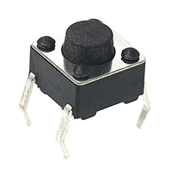
Momentary Pushbutton Switch
This is a common component for controlling electronic devices. It is mostly used to connect or disconnect control circuits, thereby enabling the control of motors or other electronic devices. A momentary pushbutton switch is normally open: when pressed, the circuit is closed; when released, it springs back to the open state.
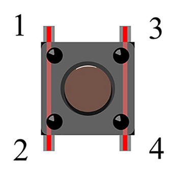
A momentary pushbutton switch has 4 pins, which can be divided into 2 groups: Pin 1 is shorted to Pin 2, and Pin 3 is shorted to Pin 4.
Experimental Steps
Hardware Connection
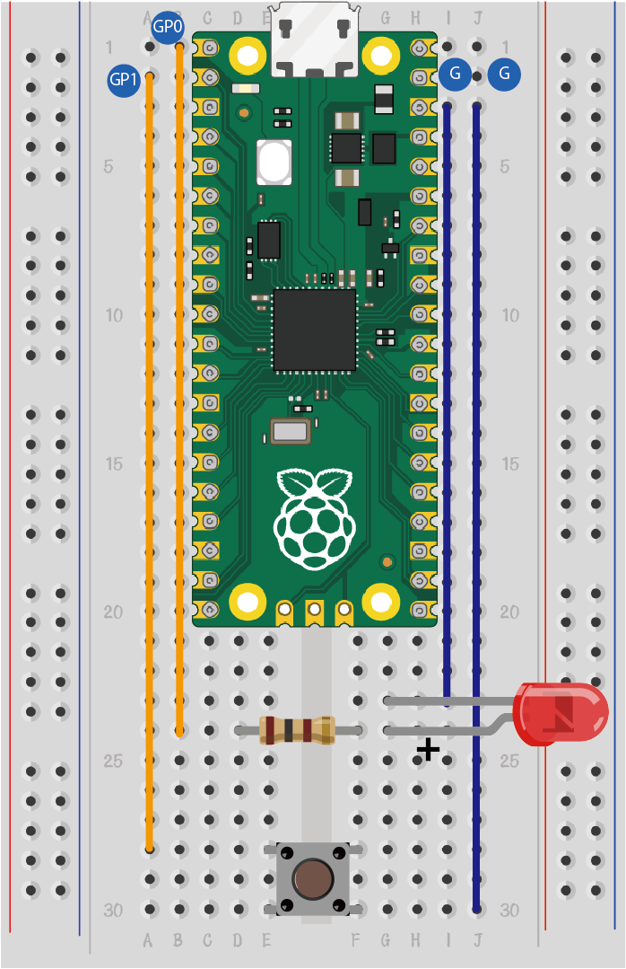
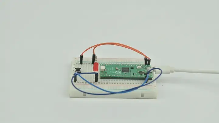
Connect your components as shown in the image below:
- Connect the short lead of the LED to GND
- Connect the long lead of the LED to pins GP0 and GP1 through resistors
- Connect the momentary pushbutton switch to pin GP2
Programming
For instructions on preparing the programming environment, please refer to: Introduction to Programming Environment
Code Example:
# Import the modules required for the program
import board
import digitalio
import time

# Set the pins and pin direction for the LEDs
led_0 = digitalio.DigitalInOut(board.GP0)
led_0.direction = digitalio.Direction.OUTPUT

# Set the pin and pull-up mode for the button
button = digitalio.DigitalInOut(board.GP1)
button.direction = digitalio.Direction.INPUT
button.pull = digitalio.Pull.UP

# Change the LED state based on the button state
while True:
    if button.value == False:
        led_0.value = True
        time.sleep(1)
        led_0.value = False
        time.sleep(1)
Code Explanation:
- Import the support modules required for the program. The board module is a universal container for pin names, allowing you to specify the pins to use via the board module. The digitalio module contains classes that provide access to basic digital I/O. The time module contains functions for time-related settings.
import board
import digitalio
import time
- Set the pins used by the breadboard expansion board to connect the LEDs, and specify the pin direction (set to output mode, as we need to send control signals to the LEDs).
# Set the pins and pin direction for the LEDs
led_0 = digitalio.DigitalInOut(board.GP0)
led_0.direction = digitalio.Direction.OUTPUT
- Set the pin for the button and enable the pull-up mode. (Pull-up mode ensures a stable high-level signal when the button is not pressed, preventing false triggers caused by external interference.)
# Set the pin and pull-up mode for the button
button = digitalio.DigitalInOut(board.GP1)
button.direction = digitalio.Direction.INPUT
button.pull = digitalio.Pull.UP
- Change the LED state based on the button state. (Detect the button's value: when the button is pressed, its value becomes False; when released, it returns to True.)
while True:
    if button.value == False:
        led_0.value = True
        time.sleep(1)
        led_0.value = False
        time.sleep(1)
Experimental Result
When you press the button, you can see the LED blink; when you release the button, the LED stops blinking. If this is not the case, please go back to the previous steps and check your operations.
Thinking
If we want to light up a red LED when the button is pressed and a green LED when the button is released, how should we program this?