Light-Dependent Resistor (LDR)

Introduction
A light-dependent resistor (LDR), also known as a photoresistor, is a type of resistor made from semiconductor materials. Its conductivity changes with the intensity of the light it receives. Using this characteristic, LDRs are manufactured in different shapes and light-receiving areas. The stronger the light, the lower the resistance of the LDR. Light-controlled switches usually use LDRs as their core component. LDRs are widely used in industries such as toys, lighting, and cameras. In this lesson, we will make the Pico:ed display different information based on the varying light intensity detected by the LDR.
Component List
Hardware
1 × Pico:ed 1 × USB Cable 1 × Breadboard Expansion Board 1 × 83 × 55mm Breadboard 1 × Light-Dependent Resistor (LDR) 1 × 10kΩ Resistor Several Dupont Wires
Introduction to Key Components
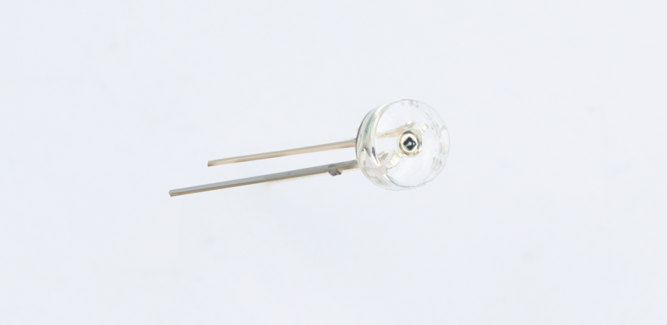
Light-Dependent Resistor (LDR)
An LDR is a special resistor made from semiconductor materials such as CdS (cadmium sulfide) or CdSe (cadmium selenide). Its working principle is based on the internal photoelectric effect. The stronger the light irradiation, the lower its resistance—its bright resistance value can be as low as 1KΩ or less. LDRs are very sensitive to light: when there is no light, they are in a high-resistance state, and their dark resistance can generally reach 1.5MΩ.
Experimental Steps
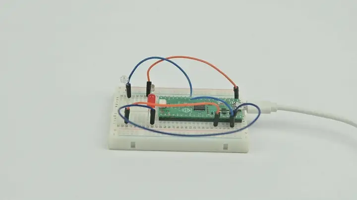
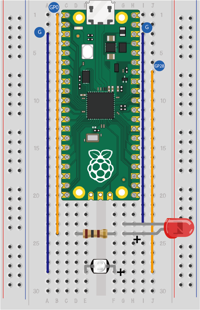
Hardware Connection
Connect your components according to the image below:
Programming
For the preparation of the programming environment, please refer to: Introduction to Programming Environment
Code Example:
# Import the modules required for the program
import board
import analogio
import digitalio
from time import *

# Set the pin connected to the photoresistor and read the analog voltage as a reference for light intensity
light = analogio.AnalogIn(board.GP28)
led_0 = digitalio.DigitalInOut(board.GP0)
led_0.direction = digitalio.Direction.OUTPUT

# Determine if the analog voltage value of the photoresistor is less than the reference value, and display different effects based on the result
while True:
    if light.value > 1000:
        led_0.value = True
    else:
        led_0.value = False
    sleep(1)
Code Explanation
- Import the support modules required for the program. The board module is a universal container for pin names, allowing you to specify the pins to use via the board library. The analogio module contains classes that provide access to analog I/O. The time module contains functions for time-related settings.
# Import the modules required for the program
import board
import analogio
import digitalio
from time import *
- Set the pin connected to the LDR and configure it to read analog voltage (which serves as a reference for light intensity). Additionally, set up the LED pin and configure its direction as output.
# Set the pin connected to the photoresistor and read the analog voltage as a reference for light intensity
light = analogio.AnalogIn(board.GP28)
led_0 = digitalio.DigitalInOut(board.GP0)
led_0.direction = digitalio.Direction.OUTPUT
- Continuously detect the analog voltage value of the LDR. Compare it with the reference value (1000 in this case) and control the LED's on/off state based on the comparison result.
# Determine if the analog voltage value of the photoresistor is less than the reference value, and display different effects based on the result
while True:
    if light.value > 1000:  # If light intensity is high (analog value exceeds 1000)
        led_0.value = True   # Turn on the LED
    else:                   # If light intensity is low (analog value is ≤ 1000)
        led_0.value = False  # Turn off the LED
    sleep(1)                # Pause for 1 second before the next detection
Experimental Result
When the light is turned on (high light intensity), the LED turns off; when the light is turned off (low light intensity), the LED turns on.