LED Lights

Introduction
LED lights are a crucial part of urban development, such as traffic lights at intersections, store billboards, park sign lights, and corridor lights in shopping malls—their applications are extremely widespread. In this lesson, we will use the Pico to control 2 LED lights and achieve an alternating blinking effect.
Component List
Hardware
1 × Pico
1 × USB Cable
1 × 83×55mm Breadboard
2 × LEDs
2 × 100-Ohm Resistors
Several Dupont Wires
Introduction to Key Components
LED
LED stands for Light Emitting Diode. It is a type of semiconductor diode that can convert electrical energy into light energy. When an electric current passes through it, the LED emits light.
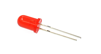
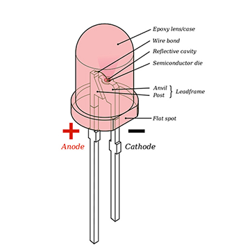
If you look closely at an LED, you will notice two features: one is that its two leads are of different lengths, and the other is that one side of the LED is flat (rather than cylindrical). These features help you distinguish between the anode (positive terminal) and the cathode (negative terminal). The longer lead connects to the positive power supply (3.3V), and the lead on the flat side connects to the negative terminal.
Resistor
A resistor is a component used to control current. It can limit the current in the connected circuit. In our experiment, we use 100-ohm resistors. Without current limiting, the LED lights would be damaged.
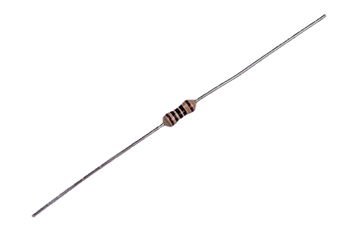
Want to identify the resistance value using color bands? You can read this article: How to Identify Color Circle Resistance Value.
Experimental Steps
Hardware Connection
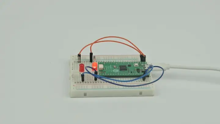
Connect your components as shown in the image below:
Connect the short lead of the LED to GND;
Connect the long lead of the LED to the P0 (GP0) and P1 (GP1) pins of the Pico through resistors.

Programming
For instructions on preparing the programming environment, please refer to: Introduction to Programming Environment
Code Example
# Import the modules required for the program
import board
from digitalio import *
from time import *

# Set the pins connected to the LEDs and the pin direction
led_0 = DigitalInOut(board.GP0)
led_1 = DigitalInOut(board.GP1)
led_0.direction = Direction.OUTPUT
led_1.direction = Direction.OUTPUT

# Set the two LEDs to switch between on and off states
while True:
    led_0.value = True
    led_1.value = False
    sleep(1)
    led_0.value = False
    led_1.value = True
    sleep(1)
Code Explanation
- Import the support modules required for the program. The board module is a universal container for pin names, allowing you to specify the pins to use via the board module. The digitalio module contains classes that provide access to basic digital I/O. The time module contains functions for time-related settings.
# Import the modules required for the program
import board
from digitalio import *
from time import *
- Set the pins connected to the two LEDs and the direction of the pins (output mode, as we need to send signals to the LEDs).
# Set the pins connected to the LEDs and the pin direction
led_0 = DigitalInOut(board.GP0)
led_1 = DigitalInOut(board.GP1)
led_0.direction = Direction.OUTPUT
led_1.direction = Direction.OUTPUT
- Use an infinite loop (while True) to switch the two LEDs between on and off states. You can also use 1 and 0 instead of True and False to set the on/off states of the LEDs (where 1/True means on and 0/False means off).
# Set the two LEDs to switch between on and off states
while True:
    led_0.value = True
    led_1.value = False
    sleep(1)  # Pause for 1 second
    led_0.value = False
    led_1.value = True
    sleep(1)  # Pause for 1 second
Experimental Result
You should see the two LEDs blinking alternately. If this is not the case, go back to the previous steps and check your operations.
Thinking
If we want to control 3 LEDs to simulate the effect of traffic lights at an intersection, how should we design the circuit and write the program?