index
Expansion Board
Introduction
Features
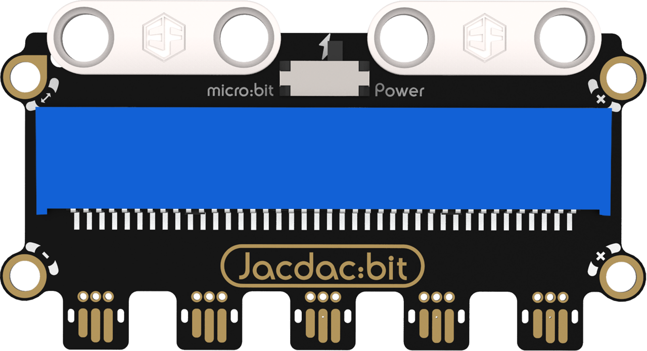
Expansion Board: The Jacdac expansion board connects to the micro:bit mainboard, providing Jacdac interfaces for the micro:bit.
Specifications
| Item | Parameter |
|---|---|
| Name | Jacdac Expansion Board |
| SKU | EF16001 |
| Product Weight | 14.3g |
| Input Rated Voltage | 3.3V |
| Output Rated Voltage | 4.15V |
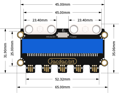
| Product Size | 65.00mm×35.06mm (L×W) |
| Jacdac Interfaces | 5 |
Appearance and Dimensions
Introduction to Jacdac Expansion Board
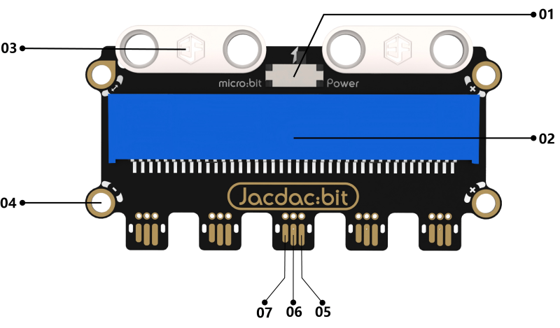
01: Power selection switch. When selecting power supply from the micro:bit to Jacdac modules, real-time feedback of Jacdac sensor values can be viewed in the device emulator of MakeCode. For an external power supply, connect a power module.
02: micro:bit socket.
03: Building block expansion structure.
04: Jacdac standard screw holes (clockwise from the mark: GND, PWR, DATA, DATA interfaces).
05: Jacdac gold finger (PWR pin).
06: Jacdac gold finger (GND pin).
07: Jacdac gold finger (DATA pin).
Product Links
None
Quick Start
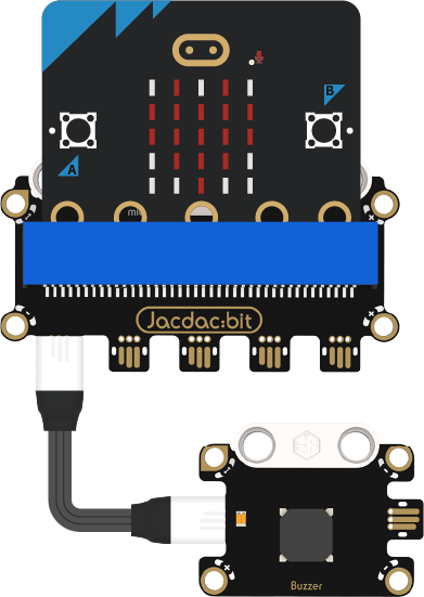
Hardware Connection Diagram
Usage Tutorials
Programming Software
MakeCode Programming
Step 1: Adding the Jacdac Extension
- Go to Microsoft MakeCode and click New Project.

- Enter a project name in the pop-up window and click Create.

- Click Extensions in the code drawer.

- Type "Jacdac" in the search bar, click the magnifying glass icon, and select the Jacdac software library as shown.

Step 2:
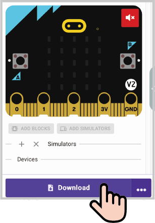
- Connect the micro:bit to your computer using a data cable. Note: If this is the first time running a Jacdac program on the micro:bit, preload a blank Jacdac program first. Skip this step if already done.
- Connect the sensor. MakeCode will automatically detect it and simulate the sensor status in the emulator.
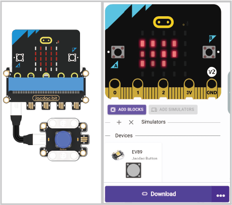
- Click ADD BLOCKS for the sensor extension module. Note: Repeat this step each time you connect a new sensor.

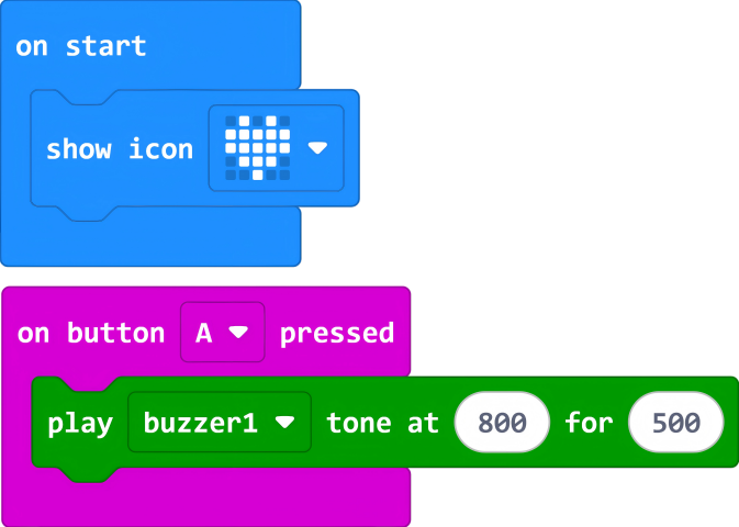
Program Code
Reference Program Link
Link: https://makecode.microbit.org/_Trw28pdDFhf4
You can also download it via the link.
