case 01 led
Introduction
LED is a common use in our life. Most of signal light employs LED as main illuminant. In this case, we will use the micro:bit to control one LED flashing.
Products Link
Hardware Connect
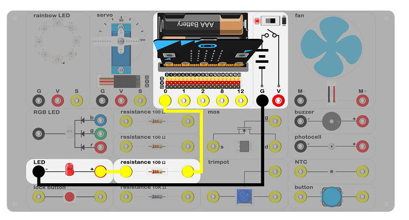 、
、
Connect the circuit as above picture and put 2 AAA batteries into the batteries pack.
Principles of Circuits

The GND of slot on the micro:bit is into innards of batteries' GND to generate the current loop. Set low voltage(digital 1) to P0, the circuit on and the LED on. Set high voltage(digital 0) to P0, the circuit off and the LED off.
Introduction of Components
LED
LED, lightemitting diode, is a solid state semiconductor devices, which can be directly converted into electricity for lighting up. The experiment box included a red LED. The black port on the left is negative pole and the red port on the right is positive pole.

Note: Please note the positive and the negative when you are connecting.
Resistor
The resistor is a kind of component to control the current. It can limit the current of connecting circuit. By the way, there is no positive or negative for the resistor. The experiment box included 3 100Ω resistors and 1 10KΩ resistor.
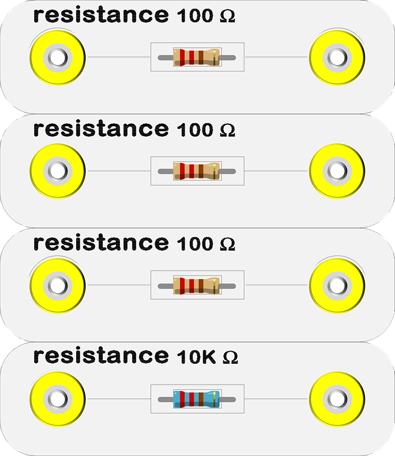
Install a 100Ω resistor in LED circuit to limit the circuit. It may cause breakdown of LED if the current is not be limited.
Software
Step 1
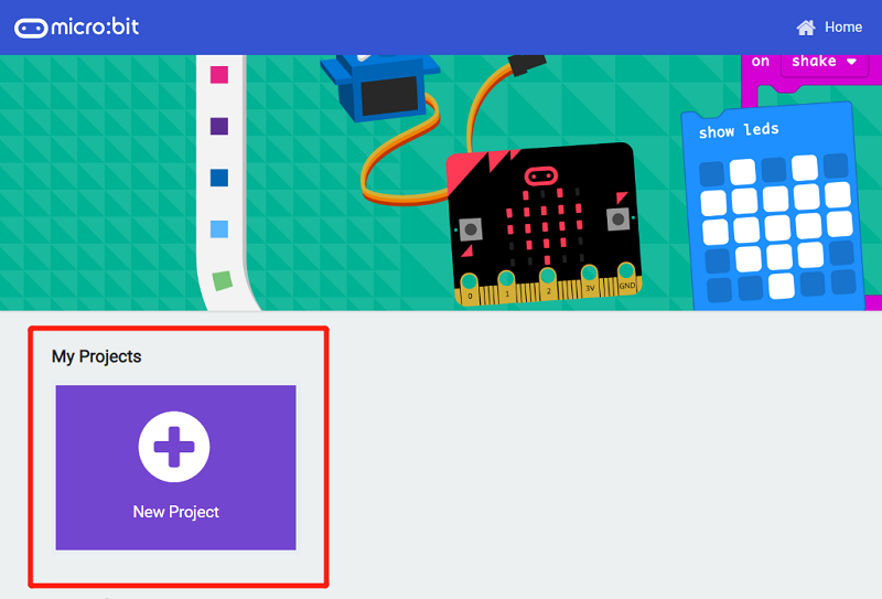
Click makecode https://makecode.microbit.org/#.
Click on "New Project" and set a new Project.
Step 2
First, snap the digital write pin into the forever block, write 1 to the P0 port for lighting up the LED, then pause 500ms;
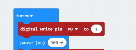
Next, snap the digital write pin under the pause (ms) block, write 0 to the P0 port for turning off the LED, then pause 500ms;

Program
Program link:https://makecode.microbit.org/_Fa1Jpj38Di1Y
You also could directly download program by visiting website as below:
Result
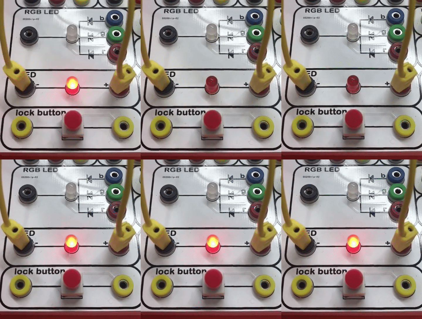
Turn on the switch, LED starts to flashing.
Think
Why we add a 500ms pause ?