Nezha For ESP32 Board
Overview
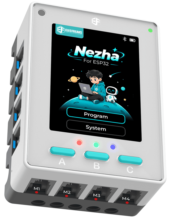
The Nezha For ESP32 Board is a core controller designed for K–12 coding education, robotics competitions, and AIoT projects.
Its modular controller-and-sensor design works with building-block systems. Students can use it for introductory coding, sensor projects, robot control, smart environmental monitoring, and creative construction. A fully enclosed housing protects the electronics, while keyed RJ11 ports and a color-coded port system help students connect sensors and expansion modules quickly in classrooms, clubs, and competitions.
The Nezha For ESP32 Board supports block-based programming with MicroBlocks, as well as MicroPython and Python. It can also connect to the Smart IoT platform for data visualization and project expansion.
SKU: EF03480
Features
Fully Enclosed Protective Housing
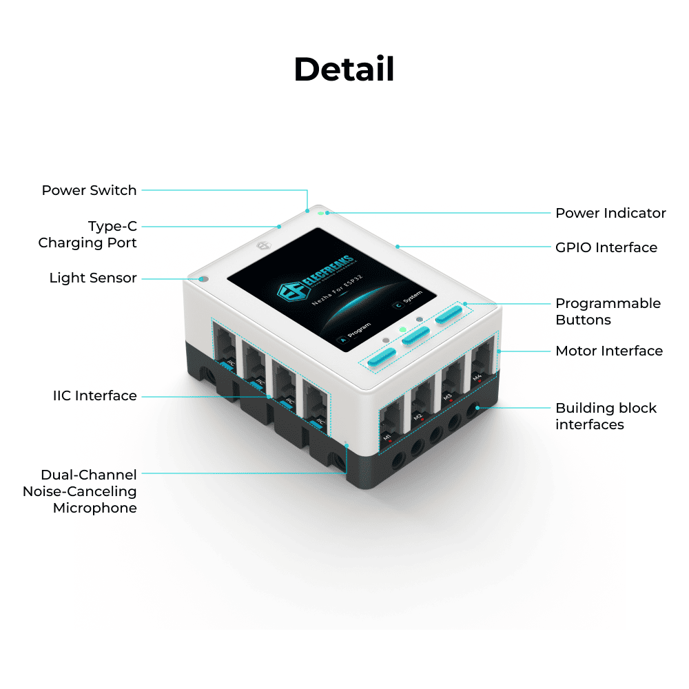
The fully enclosed housing helps reduce the risk of hardware damage caused by drops and impacts during classroom activities, model building, and competition testing.

Keyed RJ11 Ports
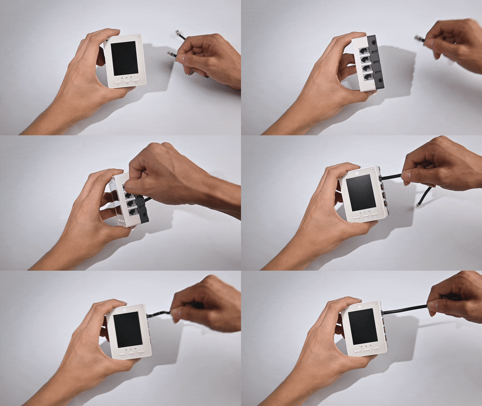
Keyed RJ11 ports help prevent reversed or incorrect connections and reduce connector wear. This design is well suited to large classes and younger learners.
Color-Coded Port System
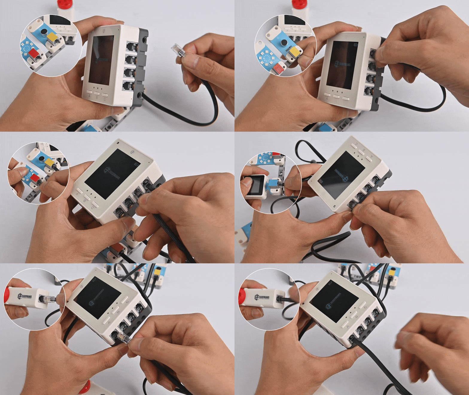
Different colors identify different port types. This helps students find the correct connection quickly and reduces classroom troubleshooting time.
| Port Color | Port Type | Description |
|---|---|---|
| Yellow | Analog / digital | Connects compatible analog or digital modules |
| Orange | Digital | Connects digital modules |
| Blue | IIC | Connects modules that use IIC communication |
| Red | Motor | Connects motors or supported actuators |
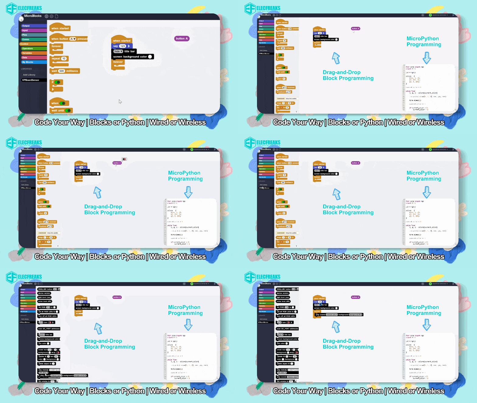
Block-Based Programming with MicroBlocks
The board supports block-based programming with MicroBlocks for K–12 coding lessons and hands-on classroom projects. Students can build programs with visual blocks and develop projects that use the controller and connected sensors.
Wired and Bluetooth Programming
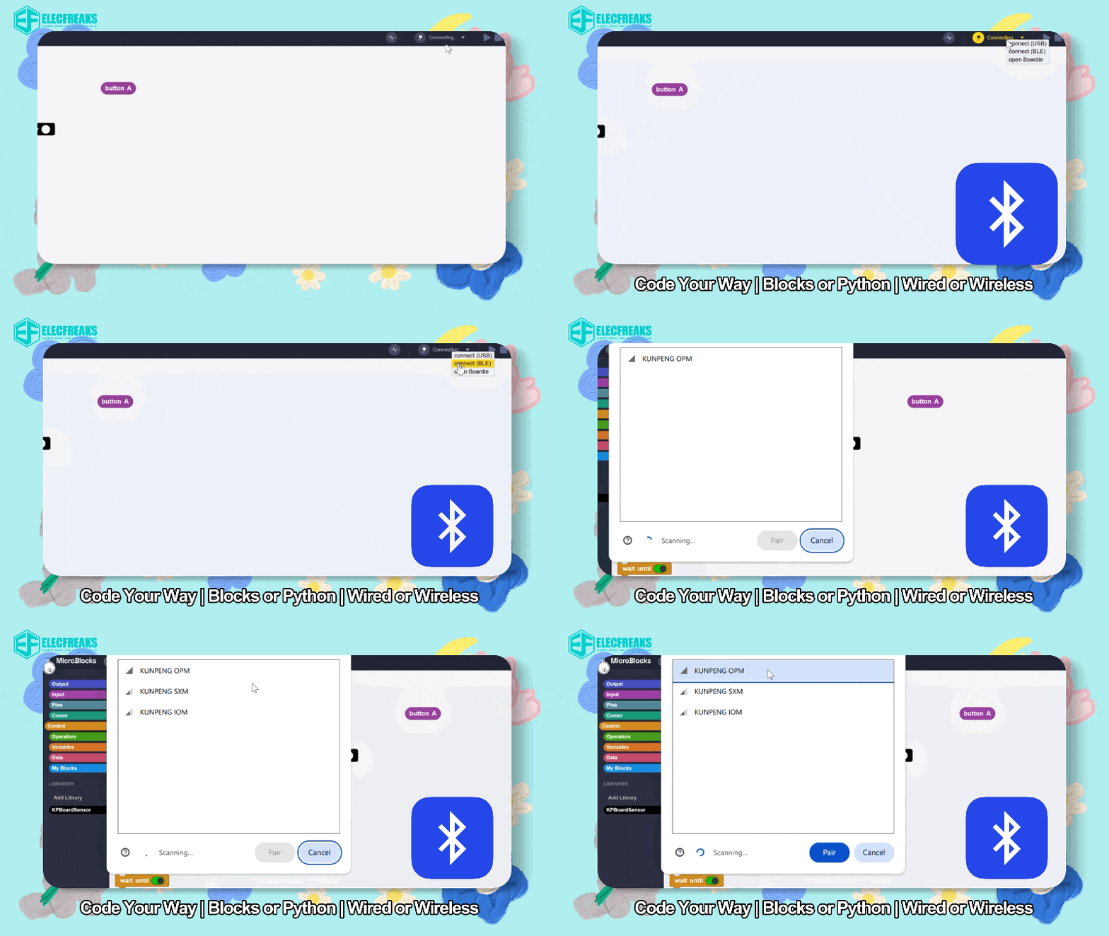
The board supports both wired and Bluetooth programming. Users can choose the most suitable connection for classroom activities or robotics competitions, reducing the need to reconnect cables during testing.
Built-In Input and Output Components
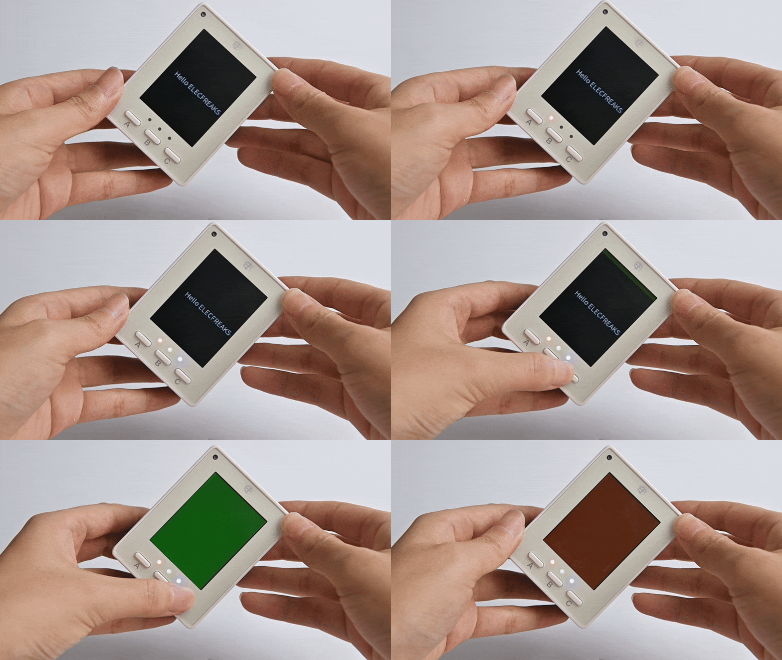
The Nezha For ESP32 Board includes essential input and output components, enabling students to complete beginner projects without external modules.
| Onboard Component | Typical Uses |
|---|---|
| 2.4-inch color display | Displays program interfaces, sensor readings, prompts, and project status |
| Three programmable buttons | Provides program input, menu navigation, and interactive control |
| Three RGB LEDs | Provides status indications, program feedback, and lighting effects |
| Ambient light sensor | Measures ambient light for projects such as automatic lighting, light logging, and sunshade alerts |
| Dual noise-reducing microphone array | Detects sound for noise monitoring, voice interaction, and AIoT projects |
| Gyroscope | Detects orientation and movement for tilt sensing, motion control, and robotics projects |
| Speaker | Provides audio feedback and notification tones |
Smart IoT Platform Support
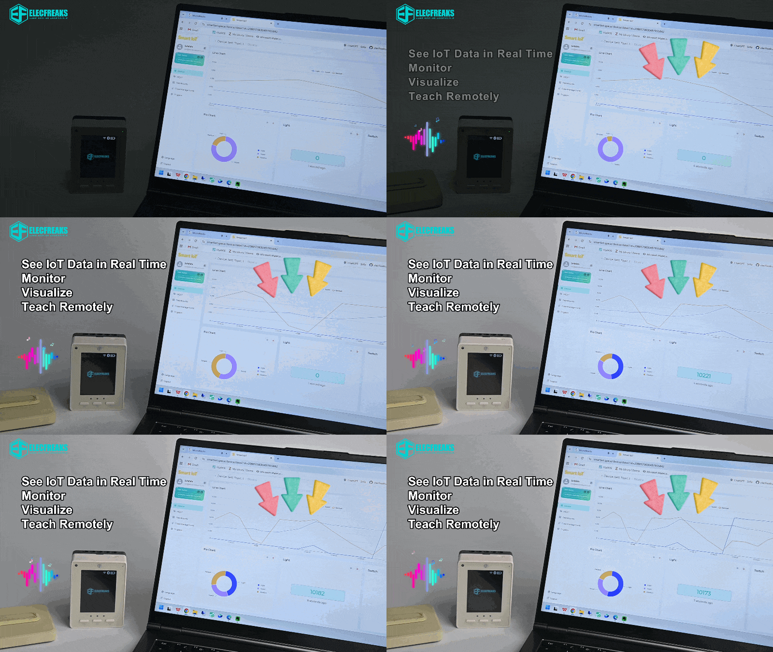
The board can connect to the Smart IoT platform. Users can create project-specific dashboards to display and record data in real time.
Support for Modular Building Systems
The board is designed to work with commonly available studded building blocks and modular beam-and-connector structural components. These parts can be used to build robots, environmental monitoring systems, smart devices, and other creative projects.
Specifications
| Item | Specification |
|---|---|
| Product Name | Nezha For ESP32 Board |
| SKU | EF03480 |
| Main Controller | ESP32-S3, dual-core, 240 MHz |
| Dimensions | 80 × 60 × 36 mm |
| Net Weight | 140 g |
| Charging Port | USB Type-C |
| Recommended Charging Input | 5 V / 3 A |
| Charging Time | Approximately 60 minutes |
| Battery | Built-in 7.4 V / 900 mAh lithium battery |
| Display | 2.4-inch, 240 × 320 color display |
| Onboard Inputs | Three programmable buttons, ambient light sensor, dual noise-reducing microphone array, and gyroscope |
| Onboard Outputs | Three RGB LEDs, speaker, and display |
| Programming Languages and Environments | MicroBlocks, MicroPython |
| Programming Connections | Wired and Bluetooth |
| IoT Support | Smart IoT platform |
| Building-System Support | Designed to work with commonly available studded building blocks and modular beam-and-connector structural components |
Power Indicator
The power indicator shows power-on, power-off, battery-level, and charging states.
| Status | Indicator Behavior |
|---|---|
| Powering on | Flashes green once |
| Powering off | Flashes red once |
| Powered off | Off |
| Battery > 50% | Solid green |
| 20% < battery ≤ 50% | Solid yellow |
| 10% < battery ≤ 20% | Solid red |
| Battery ≤ 9% | Rapid red flashing |
| Charging while powered on | Slowly flashes in the current battery-level color |
| Charging while powered off | Slowly flashes red |
| Fully charged | Solid green |
User Interface
Button Functions
The current development firmware and the planned production release use different menu controls. In user programs, all three buttons can also be assigned custom functions.
| Version | A Button | B Button | C Button |
|---|---|---|---|
| Current development version | Back | Confirm | Next option |
| Production version | Back | Switch option | Confirm |
Main Screens
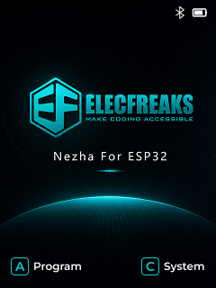
Home Screen
The default screen displayed at startup.
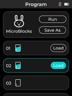
Run and Load Programs
From the Home screen, press button A once to open this page in the current development version.
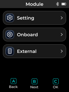
Module Selection
From the Home screen, press button C once to open this page in the current development version.
Quick Start
Open MicroBlocks
Development and testing access:
https://www.smartiot.space/microblocks/
Development note: The Smart IoT branch of MicroBlocks is intended for early-stage development, testing, and evaluation. It will be closed after the product is officially launched.
Production access after launch: https://microblocksfun.cn/run/microblocks.html
Connect the Board
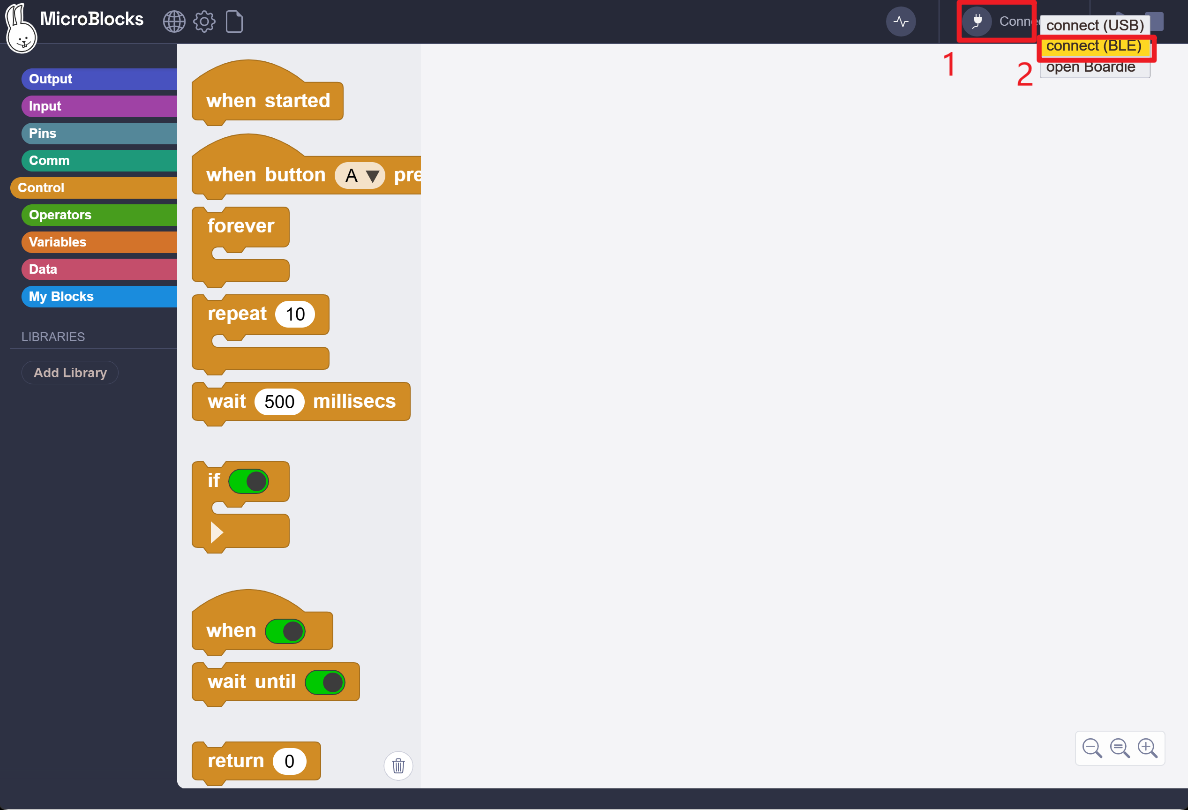
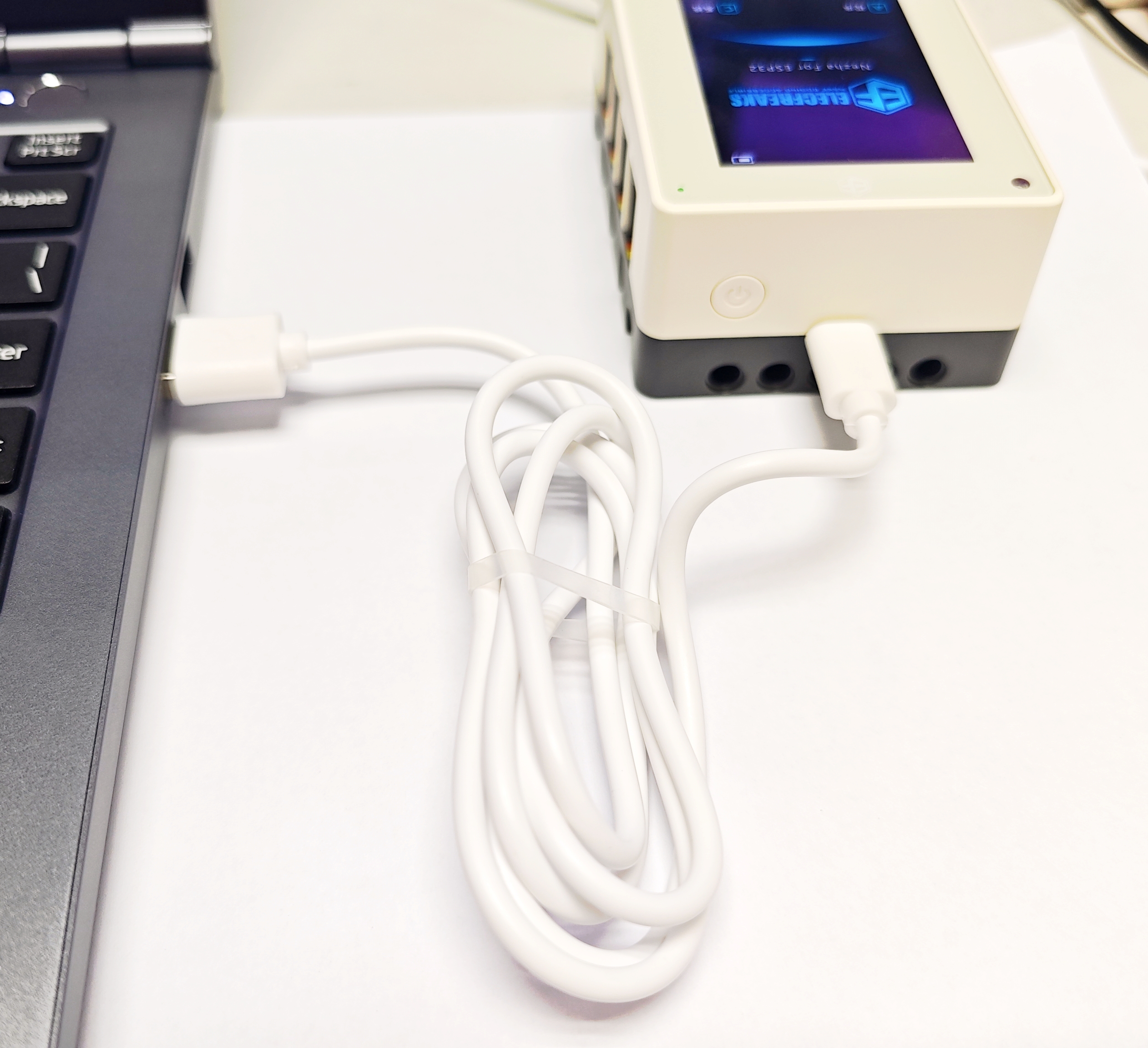
- Wired connection: Connect the Nezha For ESP32 Board to your computer with a USB Type-C data cable.
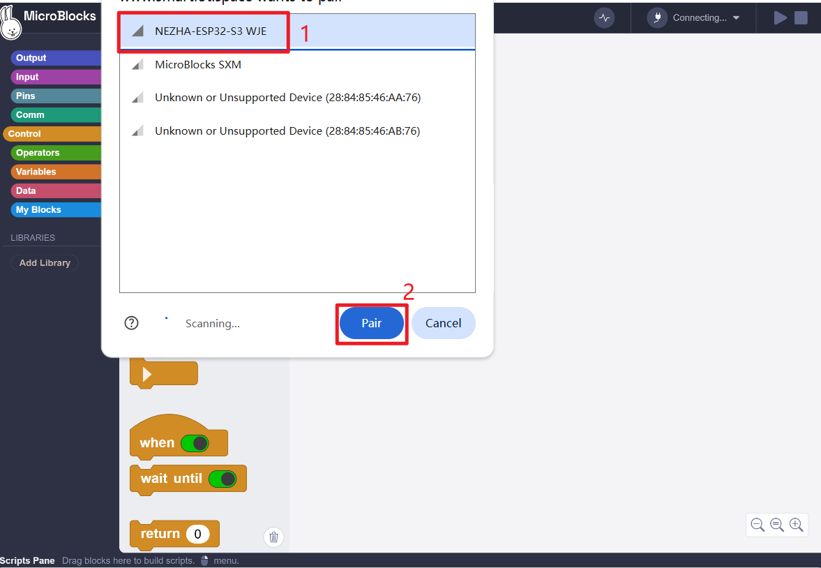
- Wireless connection: Connect the Nezha For ESP32 Board to your computer via Bluetooth.
Update the Firmware (Optional)
Follow these steps to update the firmware on the Nezha For ESP32 Board.
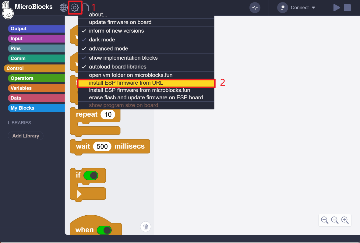
- In MicroBlocks, select the option to update firmware from a URL.
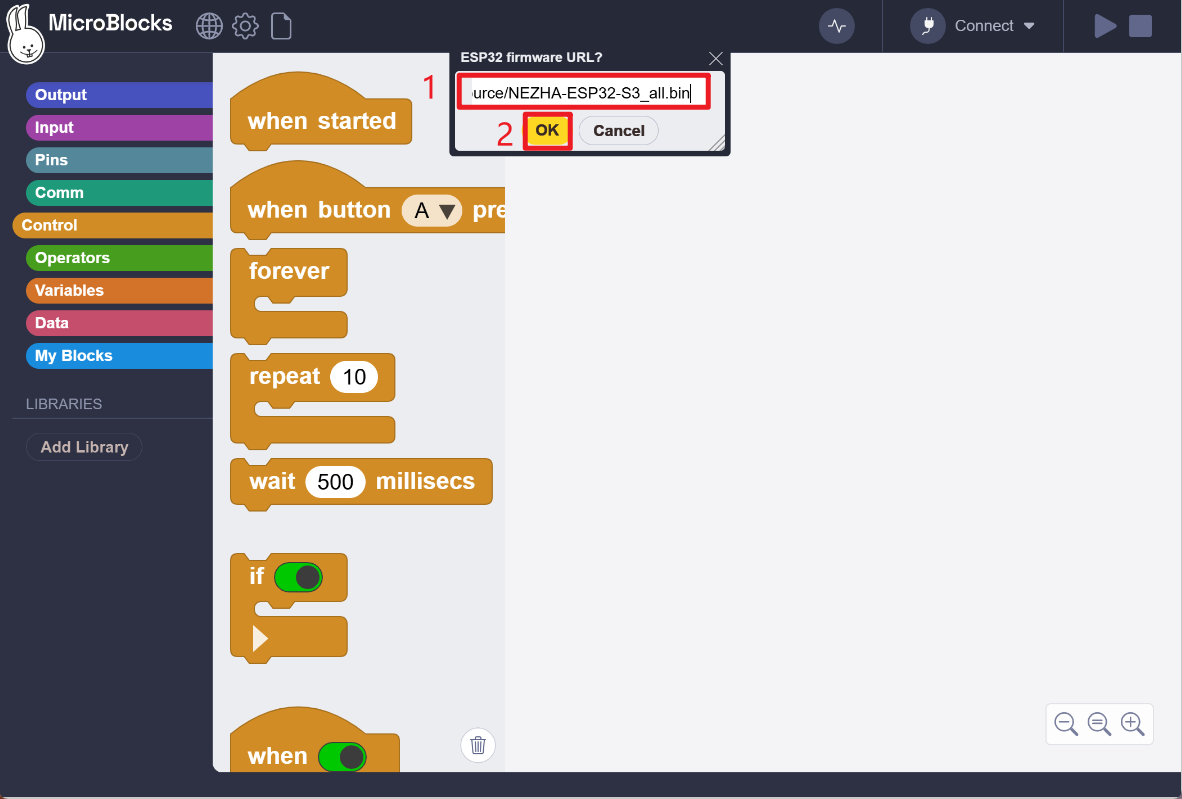
Use the following URL to download the firmware file:
Firmware version: V0.9.3
Firmware update date: 26/08/28https://www.smartiot.space/static_resource/NEZHA-ESP32-S3_all.bin
- After the firmware file has downloaded, press and hold the power button to turn on the Nezha For ESP32 Board. Connect the board to a computer with a USB-C data cable.
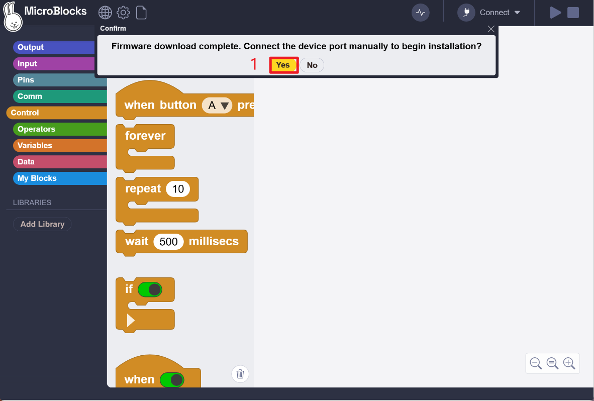
- Select the corresponding serial port to begin the firmware update.

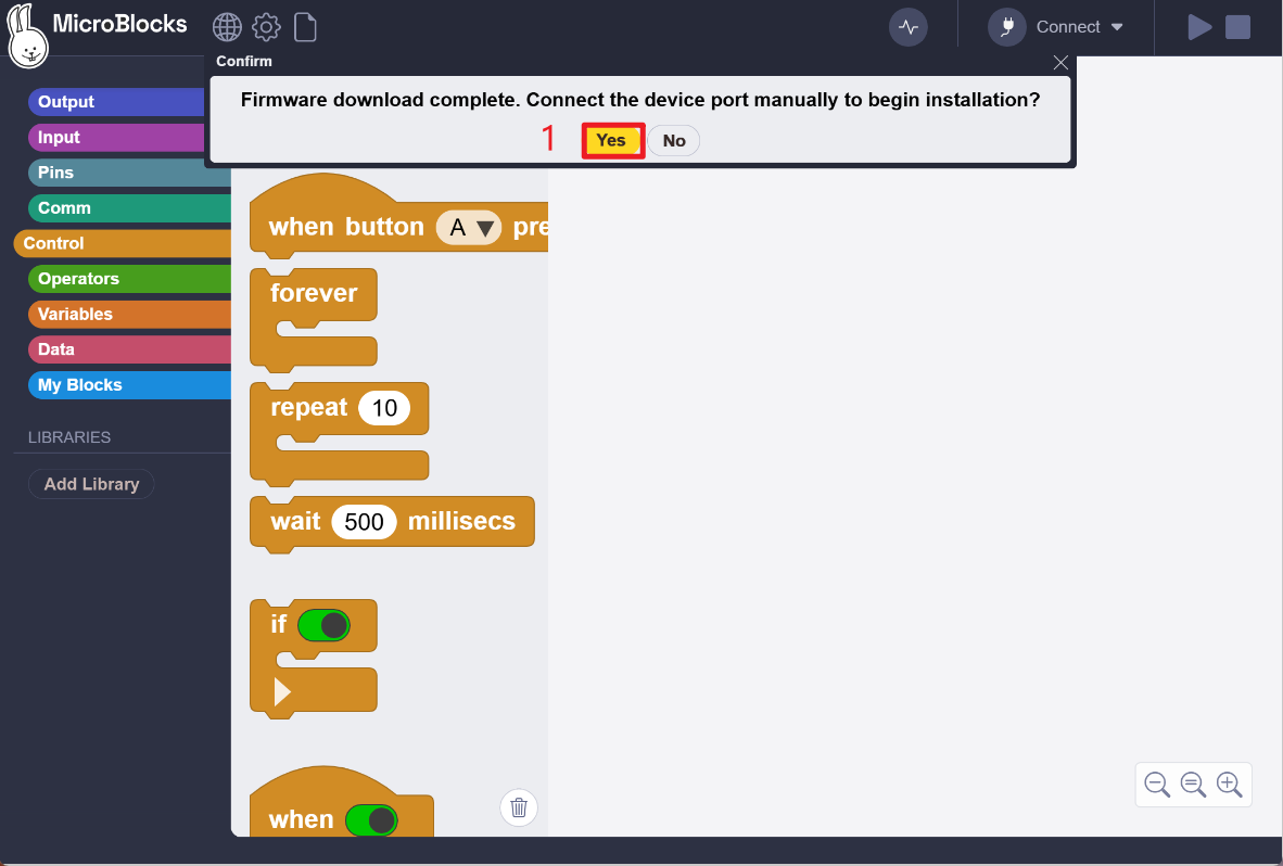
- When the update-complete message appears, disconnect the USB-C cable and restart the Nezha For ESP32 Board.
Add the Nezha ESP32 Extension Library
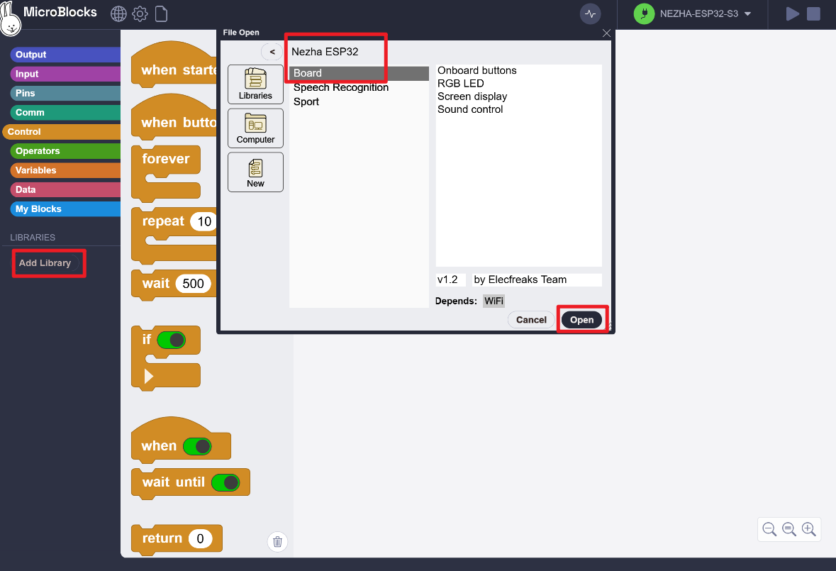
Add the dedicated extension library to use the blocks for the Nezha For ESP32 Board.
Current library path: Libraries → Elecfreaks → Nezha ESP32 → Board
Programming Block Categories
| Category | Description |
|---|---|
| Basic Control | Read device information, initialize the board, and set its operating state |
| Display | Show text, values, icons, or pages on the color display |
| Button Input | Read the state of buttons A, B, and C |
| RGB LEDs | Set the color of one or all RGB LEDs |
| Onboard Light Sensor | Read ambient light data |
| Onboard Microphone | Read sound or noise data |
| Onboard Gyroscope | Read orientation, tilt, or motion data |
| External Sensors | Read data from sensors connected through RJ11 ports |
| Motion | Control motor speed, direction, stop commands, and motion states |
| IoT Platform | Upload data to the Smart IoT platform |
Example Programs
Example 1: Light-Activated Music Alarm
This example reads the onboard ambient light sensor. When the light level reaches or exceeds 3,000 lux, the board plays music.
Example 2: Read Microphone Data and Control the RGB LEDs
This example reads data from the onboard microphone. The display continuously shows the current sound level in decibels (dB). When the sound exceeds a defined threshold, the RGB LEDs change color to provide a visual alert.
Run a Program on the Board
- Connect the board to your computer with a USB Type-C data cable or via Bluetooth.
- Select the corresponding device in MicroBlocks.
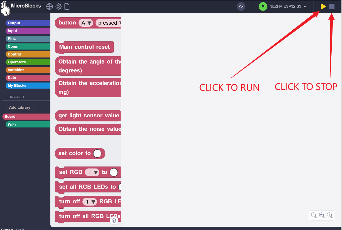
- After the connection is established, run the program or transfer it to the board.
- Confirm that the program runs correctly before disconnecting the board.
- To keep the program on the device, use the board's program storage function.
Note:
Short-press the power button to reset the program when powered on.
To save the current program, manually click "Save As" in the Program Management page of the UI.
Expected Result
After a program is transferred or started, the board can read data from onboard or external sensors according to the program logic. It can provide feedback through the display, RGB LEDs, speaker, motors, or the IoT platform.
FAQ
The computer does not recognize the board.
Make sure the USB Type-C cable supports data transfer. Try another USB port, reconnect the device, or restart the board.
MicroBlocks cannot connect to the board.
Check the browser permissions, device connection status, and USB data cable. If the problem continues, refresh the MicroBlocks page or try another cable.
A sensor is not returning data.
Make sure the RJ11 cable is fully inserted, the port color matches the module type, and the sensor is connected to the correct port.
A motor does not run.
Check the motor port, battery level, and program settings. Charge the board before continuing if the battery level is low.
Related Resources
- MicroBlocks development and testing platform: https://www.smartiot.space/microblocks/