Case 07: Little Fish Pond

Introduction
I'm sure many of you would like to have a small fish pond with lots of beautiful fish in it, but fish farming is a technical task, not only do you have to pay attention to the quality of the water but also to the level of the water, if we could detect this data in real time and tell us, then fish farming would become much easier. We used a water level sensor with LED lights to create a water level monitor.
Materials Requested
1 × Raspberry Pi Pico
1 × Wukong2040 expansion board
1 × USB cable
1 × Water level sensor
1 × Green LED
1 × Red LED
1 × Water cup
3 × 3P Dupont Cable with buckles
Introduction to main components
Water level sensor
The principle of operation of the water level sensor is very simple.
The sensor has a series of ten exposed copper wires, five of which are the power copper wires and the other five are the sensing copper wires. These traces are arranged in alternate rows so that there is a sensing copper between every two power copper traces.
Normally, these traces are not connected, but are bridged by water when immersed in water. These copper traces connected by water will have different amounts of current flow depending on how much water is submerged. It is like a variable resistor (like a potentiometer) whose resistance varies according to the water level. The change in resistance corresponds to how much the sensor is submerged.
The resistance is inversely proportional to the height of the water for the following reasons: The more water the sensor is immersed in, the better the conductivity, the lower the resistance and the greater the value of the power connected. The less water the sensor is immersed in, the less conductive it is, the higher the resistance and the lower the value of the connected power. The sensor produces an output voltage based on the resistance and by measuring this we can determine the water level.
However, pure water is not conductive, it is the minerals and impurities in the water that make it conductive. Therefore, the values obtained in your experiments may not be the same as in mine.
The same principle applies when used as a raindrop sensor, where rain drops are placed on the surface of an arrangement of copper wires, creating a connection that generates a conductive charge and a change in the analogue model.
Hardware connections
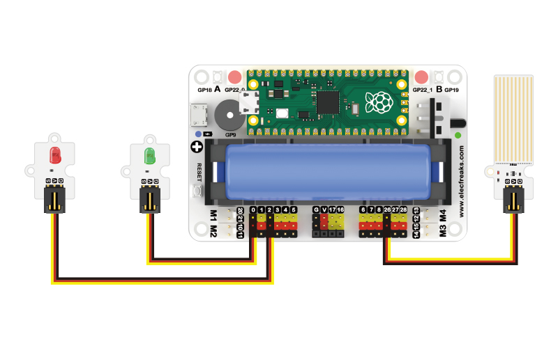
Connect your components according to the following connection diagram:
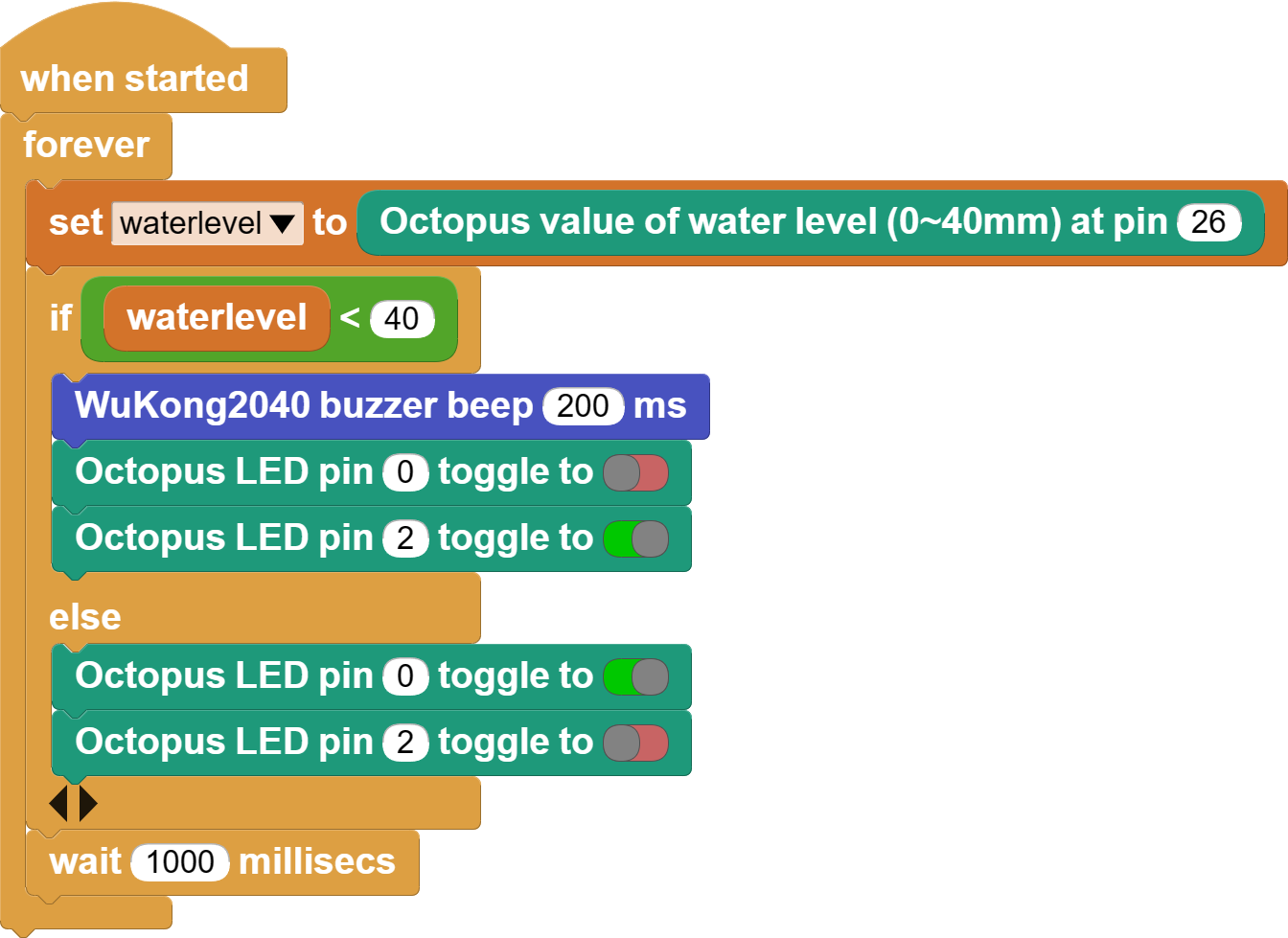
MicroBlocks Graphical Programming
CircuitPython Code
from WuKong2040 import *  # Import the WuKong2040 library and use the on-board buzzer to make sounds
from Waterlevel import *  # Import the water level sensor library and get the values returned by the water level sensors
from LED import *  # Import the LED library and set the LEDs on and off
import time  # Import time libraries to control program run interrupt times

waterlevel = Waterlevel(board.GP26)  # Create a water level sensor object and pass in the pin number
led1 = LED(board.GP0)  # Create a green light object and pass in the pin number
led2 = LED(board.GP2)  # Create red light objects and introduce pin numbers

while True:
    waterlevel_value = waterlevel.get_waterlevel()  # Assign the value returned by the water level sensor to waterlevel_value
    if waterlevel_value < 20000:
        led1.set_led(0)  # Set LED on and off, 0 for off, 1 for on
        led2.set_led(1)
        music.play(music.DADADADUM)  # Play a melody

    else:
        led1.set_led(1)
        led2.set_led(0)
    time.sleep(1)
Case display
Think
Can you add a light sensor to this case so that the red LED lights up when the light intensity reaches a certain value?